This post is the second part of the Robotics/DuckieTown series.
Code in the document is adapted from here
If you’re coding along with this tutorial, you may need the associated launch files to properly run your code. See my github repository.
Introduction
Now that we have the DuckieBot all set up from part 1, let’s try driving the it in DuckieTown! The goal of this exercise is simple and is separated into a few stages:
- Start the robot at location $(x, y, \theta) = (0.32, 0.32, \frac{\pi}{2})$ in DuckieTown.
- State 1: Stay still for 5 seconds.
- State 2:
- Rotate clockwise $\frac{\pi}{2}$ radians.
- Move straight for 1.25 metres.
- Rotate counterclockwise $\frac{\pi}{2}$ radians.
- Move straight 1.25 metres.
- Rotate counterclockwise $\frac{\pi}{2}$ radians.
- Move straight 1.25 metres.
- State 1: Stay still for 5 seconds.
- State 3: Move back to the robots initial position and orientation.
- State 1: Stay still for 5 seconds.
- State 4: Perform a clockwise circular motion around DuckieTown. Try to approach your initial position.
- Each state above should be indicated by a different LED light on the DuckieBot.
This may be a bit hard to visualize in your head. Figure 1 graphically depicts the task outlined above. In the figure, each state is denoted by a coloured circle, with a similarly coloured arrow to show where the DuckieBot should drive in this state (if applicable). If a state does not have an arrow, this means the DuckieBot should be stationary in this state. The grid underneath the DuckieBot represents DuckieTown, with each square in the grid representing a single foam mat in the real-life version of DuckieTown.
Now, while we move it’s important to keep track of the robot’s position in the world. We’ll compute this information and save it to a ROS Bag so that we can later analyze it to see where the robot thinks it is. Also, we should ensure that the robot’s angle in the world frame (denoted by $\theta$) is kept between $[0, 2\pi)$.
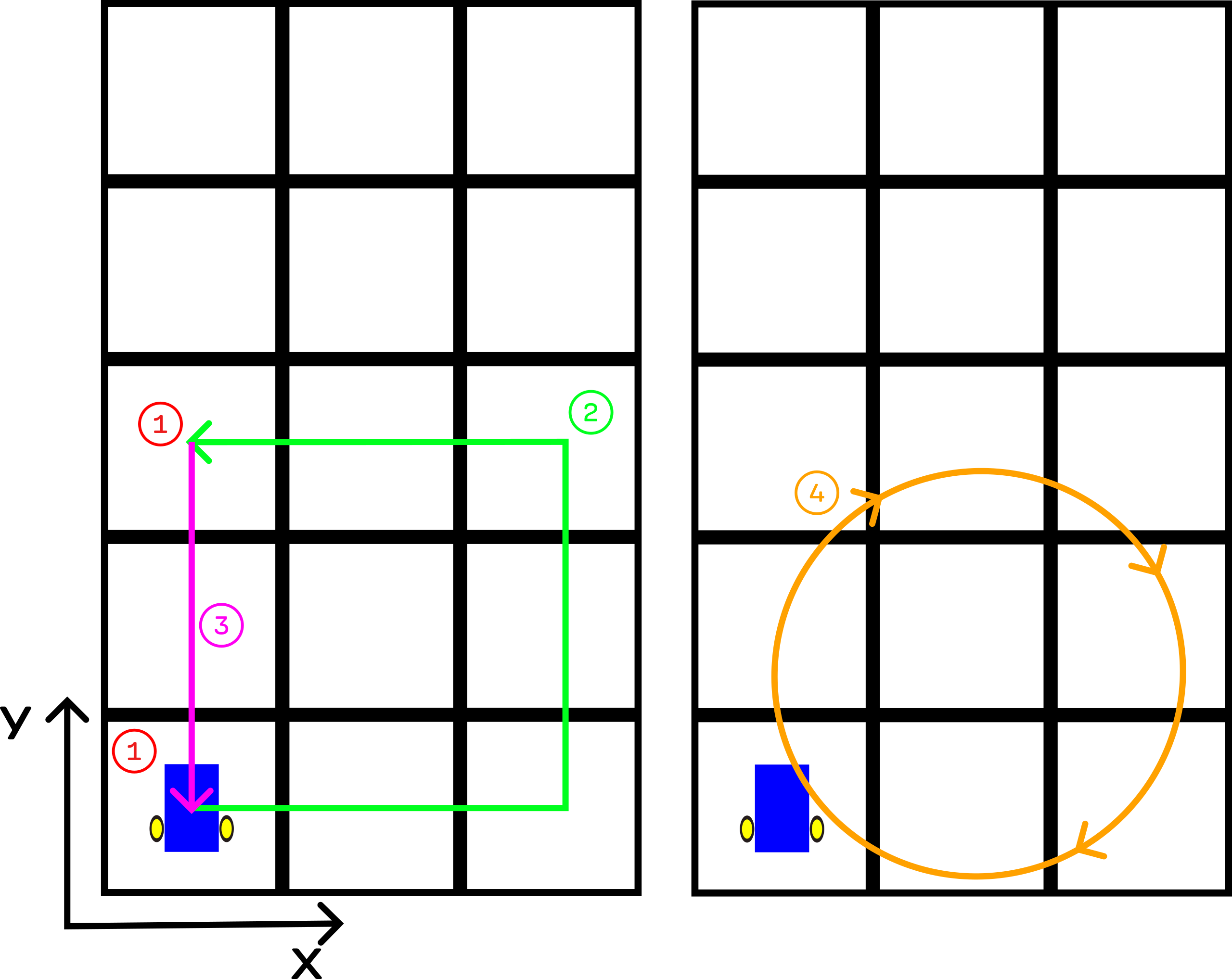 Figure 1: Visual Depiction of the Task to complete. Each state is denoted in a colour-coded circle. Each square denotes a different foam mat in the real-life constructed DuckieTown. The DuckieBot initially faces straight upwards, at an angle of 90°. The bot must then drive in a square while always facing straight ahead. Once the DuckieBot returns to its initial position, it then drives in a circle.
As usual, you can see the code for this exercise as well as a PDF of the instructions on my github repo.
Keeping Track of the Robot’s Position and Rotation in the World Frame.
In order to perform this task, we need to be able to keep track of the robots position in the world frame. How do we do this?
First, let’s get some definitions out of the way. We use $(x_r, y_r, \theta_r)$ to denote the position of the robot in the robot coordinate system (robot frame). In the robot coordinate system, the robot is always at the origin, and so $(x_r, y_r) = (0, 0)$ always. We use $(x_w, y_w, \theta_w)$ to denote the position of the robot in the world coordinate system (world frame). For conciseness I may write $(x, y, \theta)_r$ for coordinates in the robot frame and $(x, y, \theta)_w$ for coordinates in the world frame. Finally, I sometimes refer to the robot’s angle as $\theta_w$, $\theta_r$, or just $\theta$ depending on context.
Consider the initial robot frame. The initial robot frame is where the robot is initially (described in the robot coordinate system), at the very beginning of the task and is static/fixed. The robot is always at $(x_r, y_r) = (0, 0)$ in the robot frame, and we defined $\theta_r = \theta_w$, where $\theta_w$ is the angle of the robot in the world frame, and $\theta_r$ is the angle of the robot in the robot frame. So, the initial robot frame is at $\left(0, 0, \frac{\pi}{2}\right)_r = \left(0.32, 0.32, \frac{\pi}{2}\right)_w$.
One important note is that at the very beginning of the task, the position of the robot (in the robot frame) with respect to the initial robot frame is $(0, 0, 0)$. That is, when the task first starts the robot is at $(0, 0, 0)_r$ with respect to the initial robot frame.
Recall that we are starting the robot at $(x_w, y_w, \theta_w) = (0.32, 0.32, \frac{\pi}{2})$ in the world frame (world coordinate system). So, how do we transform from the initial robot frame (which is at $(0, 0, \frac{\pi}{2})_r$) to the world frame? We simply need to offset our $(x, y)$ coordinates by $(0.32, 0.32)$.
Integrating to Figure out the Position in the World Frame
Note: in writing this section, I heavily referenced [6]; this is a great resource to learn more about mobile robotics!
Now, imagine the robot has been moving around for a while. How do we figure out where it is in the world frame? Well, kinematics will tell us how to figure out how the robot frame changed with respect to the change in the world frame:
\[\begin{bmatrix} \dot x_r \\ \dot y_r \\ \dot \theta_r \end{bmatrix} = R(\theta) \begin{bmatrix} \dot x_w \\ \dot y_w \\ \dot \theta_w \end{bmatrix} = \begin{bmatrix} \cos(\theta) & \sin(\theta) & 0 \\ -\sin(\theta) & \cos(\theta) & 0 \\ 0 & 0 & 1 \end{bmatrix} \begin{bmatrix} \dot x_w \\ \dot y_w \\ \dot \theta_w \end{bmatrix}\]But, we want the opposite of this which is exactly what inverse kinematics will give us;
\[\begin{bmatrix} \dot x_w \\ \dot y_w \\ \dot \theta_w \end{bmatrix} = R^{-1}(\theta) \begin{bmatrix} \dot x_r \\ \dot y_r \\ \dot \theta_r \end{bmatrix} = \begin{bmatrix} \cos(\theta) & - \sin(\theta) & 0 \\ \sin(\theta) & \cos(\theta) & 0 \\ 0 & 0 & 1 \end{bmatrix} \begin{bmatrix} \dot x_r \\ \dot y_r \\ \dot \theta_r \end{bmatrix}\]So, now we know how the robot changes in the world frame over time. All that’s left is to integrate:
\[\begin{align} x_w &= ∫_0^T \dot x_w dt = ∫_0^T [\cos(\theta(t)) \dot x_r - \sin(\theta(t)) \dot y_r] dt \\ y_w &= ∫_0^T \dot y_w dt = ∫_0^T [\cos(\theta(t)) \dot y_r + \sin(\theta(t)) \dot x_r] dt \\ \theta_w &= ∫_0^T \dot \theta_w dt = ∫_0^T \dot \theta_r dt \end{align}\]where $T$ is the current time. I’ve written $\theta(t)$ here to make it more explicit that $\theta$ depends on time. Since our DuckieBots cannot move along the $y_r$ axis, we have $\dot y_r = 0$. Hence, the above equations become:
\[\begin{align} x_w &= ∫_0^T \dot x_w dt = ∫_0^T \cos(\theta(t)) \dot x_r dt \\ y_w &= ∫_0^T \dot y_w dt = ∫_0^T \sin(\theta(t)) \dot x_r dt \\ \theta_w &= ∫_0^T \dot \theta_w dt = ∫_0^T \dot \theta_r dt \end{align}\]And of course, we don’t actually solve these integrals explicitly but rather approximately evaluate them using sums. On each time step, we compute:
\[\begin{align} x_w &= \sum_{t=0}^T dx_w^{(t)} = \sum_{t=0}^T \cos(\theta(t)) dx_r^{(t)} \\ y_w &= \sum_{t=0}^T dy_w^{(t)} = \sum_{t=0}^T \sin(\theta(t)) dx_r^{(t)} \\ \theta_w &= \sum_{t=0}^T d\theta_w^{(t)} = \sum_{t=0}^T d\theta_r^{(t)} \end{align}\]where $dx_w^{(t)}$ is the change in $x_w$ at time $t$, $dx_r^{(t)}$ is the change in $x_r$ at time $t$, $d\theta_w^{(t)}$ is the change in $θ_w$ at time $t$, and $d\theta_r^{(t)}$ is the change in $θ_r$ at time $t$. Now, the question is, how do we actually calculate these values so that we can evaluate these sums?
It turns out there is a fairly simply formula for differential drive systems like our DuckieBots. At each step, we update our pose estimate according to the following equations:
\[\begin{align} x_w^{(t+1)} &= x_w^{(t)} + \Delta x \\ y_w^{(t+1)} &= y_w^{(t)} + \Delta y \\ \theta_w^{(t+1)} &= \theta_w^{(t)} + \Delta \theta \end{align}\]where
\[\begin{align} \Delta x &= dA \cos(\theta^{(t)}) = dx_r^{(t)} \cos(\theta^{(t)}) \\ \Delta y &= dA \sin(\theta^{(t)}) = dx_r^{(t)} \sin(\theta^{(t)}) \\ \Delta \theta &= \frac{dr - dl}{2 L} \\ dA &= \frac{dr + dl}{2} \\ 2L &= \text{distance between both wheels} \end{align}\]where $dl$ and $dr$ are the changes in distance travelled for the left and right wheel respectively (see Figure 2). If we simply use these equations to update our estimate of $(x_w, y_w, \theta_w)$ at each step, we effectively calculate the sums above. Figure 2 graphically depicts how the forward motion and rotation of the DuckieBot changes as the wheels rotate. If all these equations are confusing or you don’t understand what they mean, Figure 2 should help visualize them!
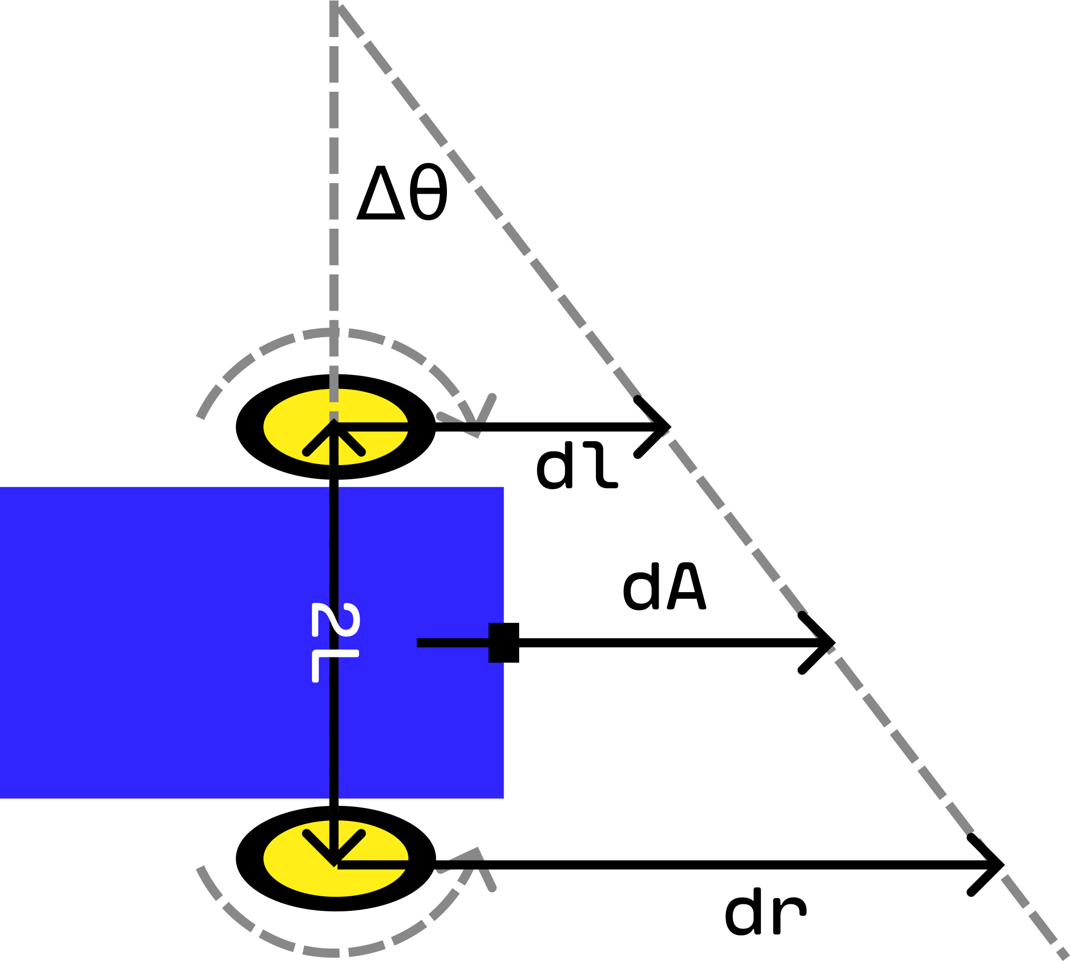 Figure 2: Calculating the Change in the World Frame. As each wheel rotates, the DuckieBot moves. The change in distance travelled by each wheel $dl$ and $dr$ can be used to calculate the change in forward motion as well as the change in rotation of the DuckieBot.
We now know how to calculate the change in the DuckieBot’s pose as its wheels rotate… but we don’t know how to determine the distance travelled by each of the DuckieBot’s wheels! How can we get $dl$ and $dr$ so that we can actually estimate the DuckieBot’s pose?
Getting $dl$ and $dr$
If you want to follow along writing your own code, you should clone the DuckieTown ROS Template and add your code there. If you don’t know how to structure your code, you should follow the DuckieTown ROS development guide before continuing.
In order to estimate the robot’s position in the world frame, we need to calculate $dl$ and $dr$.
Lucky for us, we can get these values from a ROS topic called ~/left_wheel_enocder_node/tick and ~/right_wheel_enocder_node/tick. Actually, these topics don’t give us $dl$ and $dr$ exactly, but they give us something we can use to calculate these values. The rotation of the wheel is separated into 135 ticks, and these topics tell us which tick the wheel is currently on. We can then subtract the current tick reading with the previous tick reading to get the change in the wheel rotation [7]:
where $\Delta \text{wheel}$ is the distance travelled by each wheel ($dl$ or $dr$), $N_{ticks}$ is the difference between the current tick reading and the previous one, and $N_{total}$ is the total number of ticks per rotation, 135 for the DuckieBot DB21 [7]. In Python, calculating this $\Delta \text{wheel}$ might look something like:
1
2
3
4
5
6
7
8
9
10
11
12
13
14
15
16
17
18
19
20
21
22
from duckietown_msgs.msg import WheelEncoderStamped
import numpy as np

# This code is taken and adapted from [2]

def delta_phi(encoder_msg: WheelEncoderStamped, prev_ticks):
    """
    Calculate the change in wheel rotation dl/dr based on the incoming
	message which describes the current tick reading and the previous number of
	ticks read.

	These messages can be read from the topics:
		~/left_wheel_enocder_node/tick
		~/right_wheel_enocder_node/tick
    """
    ticks = encoder_msg.data  # Current number of ticks
    delta_ticks = ticks - prev_ticks
    n_total = encoder_msg.resolution  # Total number of ticks per full rotation
    alpha = 2 * np.pi / n_total
    delta_phi = alpha * delta_ticks

    return delta_phi, ticks
This delta_phi function actually calculates $\Delta \text{wheel}$ assuming a wheel radius of $1$ (i.e. it calculates the fraction with which the the wheel rotated). To account for wheels of radii different from $1$, simply multiply the output of this function by the wheel’s radius. This will give you $dl$ and $dr$.
A Note on some Challenges I Faced
When I first implemented this code to estimate the robot’s odometry, my estimates were way off and I couldn’t figure out why. After doing some more reading on odometry with differential drive and looking at some DuckieTown source code, I realized something.
Before updating, you should wait to get a reading from each wheel topic. Don’t update if you only get a message on a single topic, if you do, then your calculation will be off. You should make sure your updates are synchronized by only updating after you get at least one message from each wheel topic.
What happens if you get multiple messages on one topic before the first message on the other topic (e.g. say we get 3 messages of the ~/left_wheel_enocder_node/tick before getting the first message on the ~/right_wheel_enocder_node/tick topic)? At first, I was just overwriting any previous messages with the latest message. This is wrong and also took me a while to figure out. What you should do is the following: if you get multiple messages about one wheel before the first message about the other, you should sum up the change in distance travelled for the first wheel, and use the sum to calculate the change in your DuckieBots position and orientation. You’ll see this later on when we implement the cb_left_encoder andcb_right_encoder functions for estimating the odometry. These functions are callbacks for Subscribers to the ~/left_wheel_enocder_node/tick and ~/right_wheel_enocder_node/tick topics respectively.
Driving in a Straight Line
Before we can actually implement the four states to solve our driving task, we need to figure out how to drive in a straight line. In order to do this, we need to utilize a ROS topic called ~/joy_mapper_node/car_cmd. This topic has type duckietown_msgs/msgs/Twist2DStamped. These messages have the following form:
1
2
3
4
5
6
7
Twist2DStamped
    Header header
        time stamp
        int seq
        ...
    float v
    float omega
where v is the velocity to apply to the DuckieBot and omega is the angular velocity to apply to the DuckieBot. The great thing about this topic is that the inverse kinematics are calculated for us.
There are two other topics you can use for this part.
Whereas I’ve use the
~/joy_mapper_node/car_cmdtopic, you can also use the~/car_cmd_switch_node/cmdtopic, which is arguably a better choice. The instructions remain the same in this post, but simply switch the~/joy_mapper_node/car_cmdtopic with~/car_cmd_switch_node/cmdtopic.There’s another topic you can use, which allows you to specify the velocity to apply to each wheel, but you’ll need to calculate the inverse kinematics yourself if you decide to go this route. The other two topics I’ve mentioned will take care of the inverse kinematics for you.
At this point our life is pretty easy, you create a publisher which publishes to ~/joy_mapper_node/car_cmd and then start publishing Twist2DStamped messages with omega = 0 and v != 0:
1
2
3
4
5
6
7
8
9
10
11
12
13
14
15
16
17
import rospy
from duckietown_msgs.msgs import Twist2DStamped


car_cmd_topic = f"~/joy_mapper_node/car_cmd"
car_cmd_pub = rospy.Publisher(
	car_cmd_topic,
	Twist2DStamped,
	queue_size=1,
	dt_topic_type=TopicType.CONTROL,
)

msg = Twist2DStamped()
msg.header.stamp = rospy.Time.now()
msg.v = 0.4

car_cmd_pub.publish(msg)
Now that I’ve told you which topic it is that can make the car move, the question is how did I find this topic? Well, that’s pretty straightforward. There’s a helpful command-line tool call rostopic. By running rostopic list you can list all the topics you can publish or subscribe to. Unfortunately, I don’t think DuckieTown has any documentation outlining what these topics do. So, it takes a big of guesswork to figure out which topic to use. I personally dove into some source code in dt-core to figure out which topic to use. But, you can also look for a topic which looks promising based off its name and then run rostopic info to get a bit more info on what the topic is. For example, running rostopic info ~/joy_mapper_node/car_cmd will give you a bunch of information on the topic ~/joy_mapper_node/car_cmd. See man rostopic for more information.
Some other useful command-line tools are
rostopic,rosservice,rosnode,rosparam,rosmsg, androssvc.
Now, if you run this code, you’ll notice something interesting. If you get your DuckieBot to drive straight for n metres, you’ll find that it isn’t exact. Sometimes the DuckieBot drive quite a bit over n metres, and sometimes it drives quite a bit under n metres. Why is this? Well, there are a number of reasons for this:
- Many sources of stochasticity exist in the DuckieBot. For example, when reading the exact motor velocities in the DuckieBot, there is some noise and the reading will never be 100% accurate.
- We are dividing wheel rotations into 135 ticks, and this limits the accuracy of the reading. For example, when the DuckieBot says that its left wheel has turned
nticks, that really means that the wheel has been rotated to be somewhere between then-thand(n+1)-sttick. The reading is not exact. - When working in the real world, there are countless sources of stochasticity that can affect the readings of the DuckieBot’s motors. For example, if there are rocks and sand in DuckieTown, this could result in the wheels slipping.
- As wheeled robots rotate, uncertainty in odometry increases.
- As speed increases, errors in odometry tend to increase.
In my code, I’ve set the speed to be maximum v = 0.4. That is, the DuckieBot moves forward with maximum velocity. I noticed that if you reduce this value, the DuckieBot tends to predict its location more accurately and therefore can better approximately drive n metres forward when requested to do so (this has to do with (5) in the list above).
To estimate the change in my DuckieBot’s position and to estimate the total change in my DuckieBot’s position over time, I used the equations in Keeping Track of the Robot’s Position and Rotation in the World Frame. This boils down to estimating the change in the DuckieBot’s $x_w$ and $y_w$ positions at each time step ($\Delta x$ and $\Delta y$) and then approximating the integration of these changes over time using the summation equations in this section.
A Note on some Challenges I Faced
As previously mentioned, DuckieTown lacks a lot of documentation and finding the right topic to publish to in order to drive the car was quite difficult. My process was originally using rostopic to list topics, search for one with a promising name, and then publish on that topic to see if it moved the DuckieBot. This took a lot of time and doing this for a while, I again jumped into some DuckieTown source code. This is where I found the ~/joy_mapper_node/car_cmd topic.
Rotating
Okay, so now we can drive straight. How can we rotate? Remember how the Twist2DStamped message takes an angular velocity to apply to the DuckieBot? Well, it’s as simple as specifying this angular velocity to be non-zero and publishing this message to the ~/joy_mapper_node/car_cmd topic:
1
2
3
4
5
6
7
8
9
10
11
12
13
14
15
16
17
import rospy
from duckietown_msgs.msgs import Twist2DStamped


car_cmd_topic = f"~/joy_mapper_node/car_cmd"
car_cmd_pub = rospy.Publisher(
	car_cmd_topic,
	Twist2DStamped,
	queue_size=1,
	dt_topic_type=TopicType.CONTROL,
)

msg = Twist2DStamped()
msg.header.stamp = rospy.Time.now()
msg.omega = 8.3

car_cmd_pub.publish(msg)
To estimate the change in my DuckieBot’s rotation and to estimate the total change in my DuckieBot’s angle over time, I used the equations in Keeping Track of the Robot’s Position and Rotation in the World Frame. This boils down to estimating the change in the DuckieBot’s angle at each time step ($\Delta \theta$) and then approximating the integration of these changes over time using the summation equations in this section.
Solving the Task
Now that we know how to drive forward and rotate, we can now implement the required functionality to solve the task described above!
The LED Service Node
The task is composed of 4 different states. To indicate which state the DuckieBot is in, we need to set the LEDs of the DuckieBot. We’re going to use a ROS Service for this. A ROS service is similar to a server. The service takes requests from clients and returns responses to those clients, similar to a web server. This allows two nodes to specifically communicate together unlike topics which are anonymous.
Constructing a ROS Service is easy. All you need is some callback function and a name for your service:
1
2
import rospy
service = rospy.Service(name, Type, callback_fn)
The callback_fn should take in TypeRequest objects and return TypeResponse objects, where Type is some ROS message type, for example the ChangePattern type allows for changing the DuckieBot LEDs using a service.
Each time the service name is called with a message msg with type Type, the callback function is executed: callback_fn(msg). How do you actually call this service in Python code?
1
2
3
4
import rospy
rospy.wait_for_service(name)  # Block until the service is available
svc = rospy.ServiceProxy(name, Type)  # Create the Python service client
svc(...)  # Call the service like a function
So to call a service, you first call wait_for_service. This is a convenience function which blocks until the service is available. Then, you create a ServiceProxy, which is like the client which calls the service for you. Then, to make calls to the service, you just call the ServiceProxy like a function. This call can take a single argument which is a TypeRequest type, where Type is the type the service expects. The call can also take in all the arguments needed to construct a TypeRequest object.
Example
This was a lot to take in, so let’s look at an example in DuckieTown.
In dts start_gui_tools, we can run rossrv info duckietown_msgs/ChangePattern to get information on the ChangePattern service message. This displays the following terminal output:
1
2
3
std_msgs/String pattern_name
  string data
---
In this message, anything above the --- is a field in the ChangePatternRequest object. Anything below the --- is also a field in the ChangePatternResponse object. So, when making requests to a service which expects type ChangePattern, we need to specify a string. The response we get will not contain any extra information.
We can make calls to this service in two ways:
1
2
3
4
5
6
7
8
9
10
11
12
13
14
15
from duckietown_msgs.srv import ChangePatternRequest, ChangePattern
import rospy
from std_msgs.msg import String

name = "~/led_emitter_node/set_pattern"  # Service for changing DuckieBot LED
svc = rospy.ServiceProxy(name, ChangePattern)

# First way to call the service, with a ChangePatternRequest object
msg = ChangePatternRequest(String("RED"))
svc(msg)

# Second way to call the service, with the arguments needed to construct a
# ChangePatternRequest
msg = String("RED")
svc(msg)
Creating the LED Changing Service
Alright, now that we know how ROS services work, let’s get back to implementing the LED changing service. We are going to have a ROS node implement this service. Since there’s already a service for changing the LED colours on the DuckieBot, we’re going to “cheat” and have our service call this service (the code below is adapted from [1]):
1
2
3
4
5
6
7
8
9
10
11
12
13
14
15
16
17
18
19
20
21
22
23
24
25
26
27
28
29
30
31
32
33
34
35
36
37
38
39
40
41
42
43
44
45
46
47
48
49
50
51
52
53
54
55
56
57
58
59
60
61
62
63
64
65
66
67
68
69
70
71
72
73
74
75
76
77
78
79
80
81
#!/usr/bin/env python3

# Adapted from [1]

from duckietown.dtros import DTROS
from duckietown_msgs.srv import ChangePattern
from duckietown_msgs.srv import ChangePatternResponse
from std_msgs.msg import String, Empty
import rospy
import time


class LightServiceNode(DTROS):
    """
    LightServiceNode implements a service for changing the colours of the the
    Duckiebot LEDs. All LEDs are kept the same colour.

    Configuration:
    Subscribers:
        ~/shutdown (:obj:`Empty`)
    Services:
        ~/light_service_node/light_change (:obj:`ChangePattern`)
    """
    def __init__(self, node_name):
        # Initialize the DTROS parent class
        super(LightServiceNode, self).__init__(node_name=node_name)

        self.veh_name = rospy.get_namespace().strip("/")

        # Duckiebots already have a service for changing LED colours, use that
        # service to change the colours when users call this node's service
        self._led_service = f"/{self.veh_name}/led_emitter_node/set_pattern"
        rospy.wait_for_service(self._led_service)
        self._embedded_svc = rospy.ServiceProxy(self._led_service, ChangePattern)

        # Subscribe to a shutdown notification topic: when we get a message on
        # this topic, shut down the node.
        shutdown_cmd_topic = f"/{self.veh_name}/shutdown"
        rospy.Subscriber(
            shutdown_cmd_topic, Empty, self._shutdown, queue_size=1,
        )

        # Create the service for changing the LED colours
        self._svc = rospy.Service(
            f"{node_name}/light_change",
            ChangePattern,
            self._change_light,
        )

        # Specify the legal colours which the LEDs can be changed to
        self._legal_colours = ["RED", "GREEN", "WHITE", "BLUE", "LIGHT_OFF"]

        self.log("light_service_node initialized.")

    def _shutdown(self, msg: Empty):
        """
        Performs the shutdown routine of the node
        """
        rospy.signal_shutdown("light_service_node: shutting down...")

    def _change_light(self, colour: ChangePattern):
        """
        Changes the LED colours of the Duckiebot
        """
        if colour.pattern_name.data not in self._legal_colours:
            rospy.loginfo(f"colour should be in {self._legal_colours} " +
                          f"but got {colour}")

        try:
            # Change the colour of the LEDs
            self._embedded_svc(colour.pattern_name)
        except rospy.ServiceException as e:
            rospy.logwarn("exception when changing LED colours: ", + str(e))

        # Tell the client that we received their request
        return ChangePatternResponse()


if __name__ == "__main__":
    led_emitter_node = LightServiceNode(node_name="light_service_node")
    rospy.spin()
The ROS Node implemented above that hosts the light changing service is called ~/light_service_node and the service itself is called ~/light_service_node/light_change. Notice also that we subscribed to a topic called ~/shutdown. When we get a message on this topic, we shut down the node. This strategy can be useful for synchronizing node shutdowns, and a similar pattern is used in the Go language to signal the shutdown of goroutines.
To call this light service node from rospy:
1
2
3
4
5
6
7
8
9
10
11
12
13
14
15
16
17
18
19
20
21
22
from duckietown_msgs.srv import ChangePattern
import rospy
from std_msgs.msg import String, Empty


# Set up the light service
svc_name = f"~/light_service_node/light_change"
rospy.wait_for_service(svc_name)  # Wait for the service to start
light_service = rospy.ServiceProxy(svc_name, ChangePattern)

# Change the LED colour to red
msg = String("RED")
light_service(msg)

# Create a publisher to signal the light service node to shut down
shutdown_cmd_topic = f"/{self.veh}/shutdown"
pub_shutdown_cmd = rospy.Publisher(
	shutdown_cmd_topic, Empty, queue_size=1,
)

# Shutdown the light service node
pub_shutdown_cmd.publish(Empty())
For more information on ROS services, see the ROS services documentation.
A Note on some Challenges I Faced
At first, I tried to create a new service for changing the LEDs from scratch. This node would have a service which could be sent an LED colour, and the node would then publish this colour to the correct topic to change the LEDs. Unfortunately, I couldn’t get this implementationto work after spending hours on it. I decided to go the easy route and just create the LED service I’ve shown above, which is a service that simply calls another service (already implemented for us) which changes the LEDs.
Another challenge I faced was that there are actually two services for changing the LED colours of the DuckieBot. One service (the one we’ve used) just takes a simple message (ChangePattern) for changing the LED. The other service is much more complicated and allows you to flash the LEDs at different frequencies as well as change the colour of each individual LED. At first, I tried to call this service from the service we implemented. Unfortunately, I couldn’t get this to work so I instead just used the simpler service, shown in the implementation above.
The Driver Node
Now it’s time to actually drive the DuckieBot and complete the task. This is fairly simple now that we have all the pieces together. First, we need to define a file odometry_activity.py which contains functions to estimate the odometry for us (the code below is taken and adapted from [2]):
1
2
3
4
5
6
7
8
9
10
11
12
13
14
15
16
17
18
19
20
21
22
23
24
25
26
27
28
29
30
31
32
33
34
35
36
37
38
39
40
41
42
43
44
45
46
47
48
49
50
51
52
53
54
55
56
57
#!/usr/bin/env python3

# This code is taken and adapted from [2]

import numpy as np
from duckietown_msgs.msg import WheelEncoderStamped

def delta_phi(encoder_msg: WheelEncoderStamped, prev_ticks):
	# This function is defined above
	pass

def estimate_pose(
    R,
    baseline_wheel2wheel,
    x_prev,
    y_prev,
    theta_prev,
    delta_phi_left,
    delta_phi_right,
):
    """
    Estimate the pose of the Duckiebot

    Parameters
    ----------
    R : float
        The radius of the wheels
    baseline_wheel2wheel : float
        The distance between the two wheels
    x_prev : float
        The previous x position of the Duckiebot
    y_prev : float
        The previous y position of the Duckiebot
    theta_prev : float
        The previous angle of the Duckiebot
    delta_phi_left : float
        The change in the left wheel
    delta_phi_right : float
        The change in the right wheel
    """
    R_left = R_right = R

    d_left = R_left * delta_phi_left
    d_right = R_right * delta_phi_right
    dA = (d_left + d_right) / 2

    dtheta = (d_right - d_left) / baseline_wheel2wheel

    dx = dA * np.cos(theta_prev)
    dy = dA * np.sin(theta_prev)

    # Update pose estimate
    x = x_prev + dx
    y = y_prev + dy
    theta = theta_prev + dtheta

    return x, y, theta, dA
Alright, now that we have the functions to estimate the odometry, all that’s left is to subscribe to the right topics, track the distance the DuckieBot has travelled, and publish the associated commands:
1
2
3
4
5
6
7
8
9
10
11
12
13
14
15
16
17
18
19
20
21
22
23
24
25
26
27
28
29
30
31
32
33
34
35
36
37
38
39
40
41
42
43
44
45
46
47
48
49
50
51
52
53
54
55
56
57
58
59
60
61
62
63
64
65
66
67
68
69
70
71
72
73
74
75
76
77
78
79
80
81
82
83
84
85
86
87
88
89
90
91
92
93
94
95
96
97
98
99
100
101
102
103
104
105
106
107
108
109
110
111
112
113
114
115
116
117
118
119
120
121
122
123
124
125
126
127
128
129
130
131
132
133
134
135
136
137
138
139
140
141
142
143
144
145
146
147
148
149
150
151
152
153
154
155
156
157
158
159
160
161
162
163
164
165
166
167
168
169
170
171
172
173
174
175
176
177
178
179
180
181
182
183
184
185
186
187
188
189
190
191
192
193
194
195
196
197
198
199
200
201
202
203
204
205
206
207
208
209
210
211
212
213
214
215
216
217
218
219
220
221
222
223
224
225
226
227
228
229
230
231
232
233
234
235
236
237
238
239
240
241
242
243
244
245
246
247
248
249
250
251
252
253
254
255
256
257
258
259
260
261
262
263
264
265
266
267
268
269
270
271
272
273
274
275
276
277
278
279
280
281
282
283
284
285
286
287
288
289
290
291
292
293
294
295
296
297
298
299
300
301
302
303
304
305
306
307
308
309
310
311
312
313
314
315
316
317
318
319
320
321
322
323
324
325
326
327
328
329
330
331
332
333
334
335
336
337
338
339
340
341
342
343
344
345
346
347
348
349
350
351
352
353
354
355
356
357
358
359
360
361
362
363
364
365
366
367
368
369
370
371
372
373
374
375
376
377
378
379
380
381
382
383
384
385
386
387
388
389
390
391
392
393
394
395
396
397
398
399
400
401
402
403
404
405
406
407
408
409
410
411
412
413
414
415
416
417
418
419
420
421
422
423
424
425
426
427
428
429
430
431
432
433
434
435
436
437
438
439
440
441
442
443
444
445
446
447
448
449
450
451
452
453
454
455
456
457
458
459
460
461
462
463
464
465
466
467
468
469
470
471
472
473
474
475
476
477
478
479
480
481
482
483
484
485
486
487
488
489
490
491
492
493
494
495
496
497
498
499
500
501
502
503
504
505
506
507
508
509
510
511
512
513
514
515
516
517
518
519
520
521
522
523
524
525
526
527
528
529
530
531
532
533
534
535
536
537
538
539
540
541
542
543
544
545
546
547
548
549
550
551
552
553
554
555
556
557
558
559
560
561
562
563
564
565
566
567
568
569
570
571
572
573
574
575
576
577
578
579
580
581
582
583
584
585
586
587
588
589
590
591
592
593
594
595
596
597
598
599
600
601
602
603
604
605
606
607
608
609
610
#!/usr/bin/env python3
# This code is taken and adapted from [2]
# Specifically, I referenced the following file heavily:
# https://github.com/duckietown/mooc-exercises/blob/daffy/modcon/solution/src/encoder_pose/src/encoder_pose_node.py
from duckietown.dtros import DTROS, NodeType, TopicType
from duckietown_msgs.msg import (
Pose2DStamped, Twist2DStamped, WheelEncoderStamped, EpisodeStart,
)
from duckietown_msgs.srv import ChangePattern
from enum import Enum
from nav_msgs.msg import Odometry
from std_msgs.msg import String, Empty
from typing import Optional
import numpy as np
import os
import rosbag
import rospy
import time
import time
import yaml
import odometry_activity
class _State(Enum):
"""
_State represents one of the four states in the exercise. If the robot is
in one of these states, it should take the actions of that state as outlined
in the exercise instructions.
"""
STOP = 1
STATE2a = 2
STATE2b = 3
STATE2c = 4
STATE2d = 5
STATE2e = 6
STATE2f = 7
STATE3a = 8
STATE3b = 9
STATE3c = 10
STATE4a = 11
STATE4b = 12
STATE4c = 13
STATE4d = 14
class EncoderPoseNode(DTROS):
"""
Computes an estimate of the Duckiebot pose using the wheel encoders and
controls the Duckiebot to perform the actions outlined in the exercise
instructions.
Args:
node_name (:obj:`str`): a unique, descriptive name for the ROS node
Configuration:
Publisher:
~/joy_mapper_node/car_cmd (:obj:`Twist2DStamped`)
~shutdown (:obj:`Empty`)
Subscribers:
~/left_wheel_encoder_node/tick (:obj:`WheelEncoderStamped`):
encoder ticks
~/right_wheel_encoder_node/tick (:obj:`WheelEncoderStamped`):
encoder ticks
Services used:
~/light_service_node/light_change (:obj:`String`)
"""
right_tick_prev: Optional[int]
left_tick_prev: Optional[int]
delta_phi_left: float
delta_phi_right: float
def __init__(self, node_name):
# Initialize the DTROS parent class
super(EncoderPoseNode, self).__init__(
node_name=node_name, node_type=NodeType.CONTROL,
)
self._state = None
self.log(f"Initializing {node_name}...")
# get the name of the robot
self.veh = rospy.get_namespace().strip("/")
# Init the parameters
self.dist = 0
self.resetParameters()
# Record the start time to ensure total run time can be calculated later
self.start_time = time.time()
# Write world frame info to a rosbag
self.world_frame_bag = rosbag.Bag(
f"/data/bags/world_frame_{self.start_time}.bag", "w",
)
# R and L:
self.R = rospy.get_param(
f'/{self.veh}/kinematics_node/radius',
0.318,
) # meters, default value of wheel radius
self.baseline = rospy.get_param(
f'/{self.veh}/kinematics_node/baseline', 0.1
) # meters, default value of baseline
# Which activities to perform:
# ODOMETRY_ACTIVITY: Calculate the odometry (useful for debugging)
# ACTIVITY: Perform the actions in the exercise
self.ODOMETRY_ACTIVITY = True
self.ACTIVITY = True
# Keep track of info for performing actions in state4
self._exited_threshold = False
self._recorded_state4_starting = False
# #####################################
# Command publishers
# #####################################
# For shutting down nodes
shutdown_cmd_topic = f"/{self.veh}/shutdown"
self.pub_shutdown_cmd = rospy.Publisher(
shutdown_cmd_topic, Empty, queue_size=1,
)
# For driving like a car
car_cmd_topic = f"/{self.veh}/joy_mapper_node/car_cmd"
self.pub_car_cmd = rospy.Publisher(
car_cmd_topic,
Twist2DStamped,
queue_size=1,
dt_topic_type=TopicType.CONTROL,
)
# Wait until the encoders data is received, then start the controller
self.duckiebot_is_moving = False
self.STOP = False
# For encoders synchronization:
self.RIGHT_RECEIVED = False
self.LEFT_RECEIVED = False
# ####################################
# Defining subscribers:
# ####################################
# Wheel encoder subscriber:
left_encoder_topic = f"/{self.veh}/left_wheel_encoder_node/tick"
rospy.Subscriber(
left_encoder_topic,
WheelEncoderStamped,
self.cb_left_encoder,
queue_size=1,
)
# Wheel encoder subscriber:
right_encoder_topic = f"/{self.veh}/right_wheel_encoder_node/tick"
rospy.Subscriber(
right_encoder_topic,
WheelEncoderStamped,
self.cb_right_encoder,
queue_size=1,
)
# ########################################
# Set the service for changing LED colour
# ########################################
self._svc_name = f"/{self.veh}/light_service_node/light_change"
rospy.wait_for_service(self._svc_name)
self._light_service = rospy.ServiceProxy(self._svc_name, ChangePattern)
# ########################################
# Set the colours of different states
# ########################################
self._stop_state_light = String("RED")
self._state2_light = String("GREEN")
self._state3_light = String("BLUE")
self._state4_light = String("WHITE")
self._light_colour = {
_State.STOP: self._stop_state_light,
_State.STATE2a: self._state2_light,
_State.STATE2b: self._state2_light,
_State.STATE2c: self._state2_light,
_State.STATE2d: self._state2_light,
_State.STATE2e: self._state2_light,
_State.STATE2f: self._state2_light,
_State.STATE3a: self._state3_light,
_State.STATE3b: self._state3_light,
_State.STATE3c: self._state3_light,
_State.STATE4a: self._state4_light,
_State.STATE4b: self._state4_light,
_State.STATE4c: self._state4_light,
_State.STATE4d: self._state4_light,
}
# Set the velocity for moving
self.steer_gain = 5.5
self.speed_gain = 0.4
# Start in the stopped state and wait for 5 seconds, the proceed to
# state 2a
self._stop()
self._set_state(_State.STATE2a)
self.log(f"{node_name} initialized.")
def resetParameters(self):
"""
Resets the parameters at the beginning of the exercise
"""
# Change in left/right wheel (metres) since previous reading
self.delta_phi_left = 0.0
self.delta_phi_right = 0.0
# Last number of wheel encoder ticks read, needed to compute
# delta_phi_{left,right}
self.left_tick_prev = None
self.right_tick_prev = None
# Initialize the odometry and total distance travelled
self.x_prev = 0.32
self.y_prev = 0.32
self.theta_prev = np.deg2rad(90)
self.dist = 0
self.x_curr = 0.32
self.y_curr = 0.32
self.theta_curr = np.deg2rad(90)
def cb_left_encoder(self, encoder_msg):
"""
Left wheel encoder callback
Args:
encoder_msg (:obj:`WheelEncoderStamped`) encoder ROS message.
"""
# Do nothing if the activity is not set
if not (self.ODOMETRY_ACTIVITY or self.ACTIVITY):
return
# If we have not yet read ticks for the wheel, read them now so that we
# can calculate φ̇ₗ later
if self.left_tick_prev is None:
ticks = encoder_msg.data
self.left_tick_prev = ticks
return
# Calculate the rotation of the left wheel, accumulating previously read
# rotations. Accumulated values are set to 0 after the pose is
# calculated.
delta_phi_left, self.left_tick_prev = odometry_activity.delta_phi(
encoder_msg, self.left_tick_prev,
)
self.delta_phi_left += delta_phi_left
# Compute the new pose
self.LEFT_RECEIVED = True
self.calculate_pose()
def cb_right_encoder(self, encoder_msg):
"""
Right wheel encoder callback, the rotation of the wheel.
Args:
encoder_msg (:obj:`WheelEncoderStamped`) encoder ROS message.
"""
# Do nothing if the activity is not set
if not (self.ODOMETRY_ACTIVITY or self.ACTIVITY):
return
# If we have not yet read ticks for the wheel, read them now so that we
# can calculate φ̇ᵣ later
if self.right_tick_prev is None:
ticks = encoder_msg.data
self.right_tick_prev = ticks
return
# Calculate the rotation of the right wheel, accumulating previously
# read rotations. Accumulated values are set to 0 after the pose is
# calculated.
delta_phi_right, self.right_tick_prev = odometry_activity.delta_phi(
encoder_msg, self.right_tick_prev,
)
self.delta_phi_right += delta_phi_right
# compute the new pose
self.RIGHT_RECEIVED = True
self.calculate_pose()
def calculate_pose(self):
"""
Calculate the pose of the Duckiebot given by the kinematics model using
the encoders.
"""
if self.STOP or not (self.LEFT_RECEIVED and self.RIGHT_RECEIVED):
return
# Sync incoming messages from encoders
self.LEFT_RECEIVED = self.RIGHT_RECEIVED = False
self.x_curr, self.y_curr, theta_curr, dA = \
odometry_activity.estimate_pose(
self.R,
self.baseline,
self.x_prev,
self.y_prev,
self.theta_prev,
self.delta_phi_left,
self.delta_phi_right,
)
self.dist += np.abs(dA)
# Clamp the angle to stay in [0, 2π)
self.theta_curr = self.angle_clamp(theta_curr)
# Save world frame data to a rosbag
pose = Pose2DStamped()
pose.header.stamp = rospy.Time.now()
pose.x = self.x_curr
pose.y = self.y_curr
pose.theta = self.theta_curr
self.world_frame_bag.write("world_frame", pose)
# Log the current angle in degrees
self.log(f"θ : {np.rad2deg(self.theta_curr)} deg")
self.log("")
self.duckiebot_is_moving = (
abs(self.delta_phi_left) > 0 or
abs(self.delta_phi_right) > 0
)
# Reset the change in wheels to calculate the new odometry only when new
# data from the encoders arrives. We want to calculate the odometry
# based on an instant in time (i.e. the change in right/left wheels
# w.r.t. time φ̇ᵣ and φ̇ₗ).
self.delta_phi_left = self.delta_phi_right = 0
# Update our estimation of the pose. Current estimate becomes previous
# estimate at next iteration.
self.x_prev = self.x_curr
self.y_prev = self.y_curr
self.theta_prev = self.theta_curr
# Run the controller only in appropriate activities
if self.ACTIVITY and self._state is not None:
rospy.loginfo(f"=== State: {self._state}")
self.Controller()
def Controller(self):
"""
Perform the control actions required by the exercise
"""
time_now = time.time()
self.time = time_now
if self._state in (
_State.STATE2a, _State.STATE2b, _State.STATE2c, _State.STATE2d,
_State.STATE2e, _State.STATE2f,
):
self._do_state2()
elif self._state in (_State.STATE3a, _State.STATE3b, _State.STATE3c):
self._do_state3()
elif self._state in (
_State.STATE4a, _State.STATE4b, _State.STATE4c, _State.STATE4d
):
self._do_state4()
else:
rospy.logerror(f"unknown state {self._state}")
pass
def _do_state2(self):
# Rotate right 90° - to angle 0°
if self._state == _State.STATE2a:
deg_threshold = np.deg2rad(15)
if self.theta_curr > deg_threshold:
v = -0.2
omega = -self.steer_gain
self.publishCmd((v, omega))
else:
self.publishCmd((0, 0))
self._set_state(_State.STATE2b)
return
# Drive straight for 1.25 metres
if self._state == _State.STATE2b:
dist_threshold = 0.08
drive = self.dist < 1.25 - dist_threshold
if drive:
v, omega = self.speed_gain, -0.2 # -0.25
if self.theta_curr > 350:
omega = 0.1
elif self.theta_curr > 5:
omega = -0.30
self.publishCmd((v, omega))
else:
self.publishCmd((0, 0))
self._set_state(_State.STATE2c)
return
# Rotate left 90° - to angle 90°
if self._state == _State.STATE2c:
deg_threshold = np.deg2rad(55)
if self.theta_curr < deg_threshold:
v = 0
omega = self.steer_gain
self.publishCmd((v, omega))
else:
self.publishCmd((0, 0))
self._set_state(_State.STATE2d)
return
# Drive straight for 1.25 metres
if self._state == _State.STATE2d:
dist_threshold = 0.25
drive = self.dist < 2.5 - dist_threshold
if drive:
v, omega = self.speed_gain, -0.2 #-0.25
if self.theta_curr < np.deg2rad(80):
omega = 0.1
elif self.theta_curr > np.deg2rad(90):
omega = -0.30
self.publishCmd((v, omega))
else:
self.publishCmd((0, 0))
self._set_state(_State.STATE2e)
return
# Rotate left 90° - to angle 180°
if self._state == _State.STATE2e:
deg_threshold = np.deg2rad(140)
if self.theta_curr < deg_threshold:
v = 0
omega = self.steer_gain
self.publishCmd((v, omega))
else:
self.publishCmd((0, 0))
self._set_state(_State.STATE2f)
return
# Drive straight for 1.25 metres
if self._state == _State.STATE2f:
dist_threshold = 0.35
drive = self.dist < 3.75 - dist_threshold
if drive:
v, omega = self.speed_gain, -0.17 #-0.25
if self.theta_curr < np.deg2rad(170):
omega = 0.25
elif self.theta_curr > np.deg2rad(190):
omega = -0.25
self.publishCmd((v, omega))
else:
self.publishCmd((0, 0))
self._stop()
self._set_state(_State.STATE3a)
return
def _do_state3(self):
# Rotate left 90° - to angle 270°
if self._state == _State.STATE3a:
deg_threshold = np.deg2rad(220)
if self.theta_curr < deg_threshold:
v = 0.1
omega = 7.0
self.publishCmd((v, omega))
else:
self.publishCmd((0, 0))
self._set_state(_State.STATE3b)
return
# Drive straight for 1.25 metres
if self._state == _State.STATE3b:
dist_threshold = 0.4
drive = self.dist < 5.0 - dist_threshold
if drive:
v, omega = self.speed_gain, -0.30 # -0.25
if self.theta_curr < np.deg2rad(90):
omega = 0.1
elif self.theta_curr > np.deg2rad(90):
omega = -0.45
self.publishCmd((v, omega))
else:
self.publishCmd((0, 0))
self._set_state(_State.STATE3c)
return
# Rotate to 180° in the negative direction - to angle 90°
if self._state == _State.STATE3c:
deg_threshold = np.deg2rad(99)
if self.theta_curr > deg_threshold:
v = 0.1
omega = -7.0
self.publishCmd((v, omega))
else:
self.publishCmd((0, 0))
self._set_state(_State.STATE4a)
return
def _do_state4(self):
if not self._recorded_state4_starting:
# Record the starting position for state4 so we can try to get back
# to it
self._s4_x0 = self.x_curr
self._s4_y0 = self.y_curr
self._recorded_state4_starting = True
# Check whether the Duckiebot is close to the starting (x, y),
# We consider the Duckiebot "close" to the starting position if it is
# within circle of radius `xy_thresh` metres of the starting position.
# Call this the "threshold region".
xy_thresh = 0.4
rad = (
(self.x_curr - self._s4_x0) ** 2 +
(self.y_curr - self._s4_y0) ** 2
)
in_threshold = rad < xy_thresh ** 2
if not in_threshold and not self._exited_threshold:
# Record whether we exited the threshold region around the starting
# (x, y). We exited the threshold if (1) we are currently outside
# the threshold region and (2) we were just inside the threshold
# region at the previous time step
self._exited_threshold = True
if self._exited_threshold and in_threshold:
# If we re-entered the threshold region, then stop
self.publishCmd((0, 0))
total_time = time.time() - self.start_time
# Log our current position and total execution time
rospy.loginfo(f"Total execution time: {total_time}")
rospy.loginfo("Final Location in World Frame:")
rospy.loginfo(f"\tx: {self.x_curr}")
rospy.loginfo(f"\ty: {self.y_curr}")
rospy.loginfo(f"\tθ: {self.theta_curr}")
self.world_frame_bag.close()
# Signal shutdown to remaining active nodes
self.pub_shutdown_cmd.publish(Empty())
rospy.signal_shutdown("done!")
# Perform actions for state 4
elif self._state == _State.STATE4a:
v, omega = 0.4, 0
dist_thresh = 0.1
if self.dist > (1.25 - dist_thresh) / 2:
self._set_state(_State.STATE4b)
elif self._state == _State.STATE4b:
v, omega = 0.4, -2.0
if 190 < np.rad2deg(self.theta_curr) < 170:
self._set_state(_State.STATE4c)
elif self._state == _State.STATE4c:
v, omega = 0.4, 0
self.publishCmd((v, omega))
def publishCmd(self, u):
"""
Publishes a car command message.
"""
car_control_msg = Twist2DStamped()
car_control_msg.header.stamp = rospy.Time.now()
car_control_msg.v = u[0] # v
car_control_msg.omega = u[1] # omega
self.pub_car_cmd.publish(car_control_msg)
def angle_clamp(self, theta):
"""
Clamp the input angle `theta` to be in `[0, 2π)`.
"""
if theta >= 2 * np.pi:
return theta - 2 * np.pi
elif theta < 0:
return theta + 2 * np.pi
else:
return theta
def _stop(self):
"""
Perform the stop state: change LEDs to red and stop for 5 seconds
"""
self._set_state(_State.STOP)
def _set_state(self, state: _State):
"""
Set the state of the robot (i.e. the states described in the exercise
instructions) and change the LED to the corresponding colour.
"""
rospy.loginfo(f"=== Setting state {state}")
self._state = state
msg = self._light_colour[self._state]
self._light_service(msg)
if state == _State.STOP:
rospy.sleep(5.)
if __name__ == "__main__":
encoder_pose_node = EncoderPoseNode(node_name="encoder_pose_node")
rospy.spin()
Note that there are quite a few hard-coded values for velocity, angular velocity, and other parameters. I’ve tuned these to work specifically for my DuckieBot and you should tune them to work with yours.
Running the Code
After running the code (and a while recording videos), I was able to get the DuckieBot to successfully perform the task. I’ve included two videos of the DuckieBot completing the task below. One thing to notice in these videos is that the DuckieBot does not exactly drive in a straight line nor does it exactly turn $\frac{\pi}{2}$ radians when requested to do so. This has to do with the reasons discussed in Driving in a Straight Line.
Furthermore, this can also be attributed to the way we’ve coded this program. We are using open-loop control, meaning that the DuckieBot is not using its sensors to adjust how it drives. If we had used a closed-loop controller, we could have used the DuckieBot’s sensors to improve its driving and adjust for inaccuracies in driving (such as veering to one side of the lane). For example, with closed-loop control we could have accounted for the lanes in DuckieTown to ensure that the DuckieBot would stay in its proper lane while driving.
Analyzing the ROS Bag
If you also ran the code above, you should have a ROS bag stored on your DuckieBot with filename /data/bags/world_frame_{n}, where {n} is replaced with the Unix time at which you ran the code. This ROS bag stored the robot’s estimated pose in the world frame $(x, y, \theta)_w$ at each time step. Let’s analyze the data here! To begin, download the ROS bag from you DuckieBot. You can use the sftp or scp commands for this. In this section, I’ll be plotting the data from the ROS Bag for the first video above, entitled “DuckieBot Driving Around DuckieTown (Open-Loop Control)”. You can get a copy of the ROS Bag I’m using here.
The following code will plot animations of the robot’s estimation of $(x, y)_w$ and $\theta_w$ over time:
1
2
3
4
5
6
7
8
9
10
11
12
13
14
15
16
17
18
19
20
21
22
23
24
25
26
27
28
29
30
31
32
33
34
35
36
37
38
39
40
41
42
43
44
45
46
47
48
49
50
51
52
53
54
55
56
57
58
59
60
61
62
63
64
65
66
67
68
69
70
71
72
73
74
75
76
77
78
79
80
81
82
83
84
85
86
87
88
89
90
91
92
93
94
95
96
97
98
99
100
101
102
103
#!/usr/bin/env python3

from matplotlib import animation
import matplotlib.pyplot as plt
import numpy as np
import rosbag
from os.path import expanduser


def animate_theta(i):
    ax.cla()  # clear the previous image
    ax.set_xlim((0, len(theta)))
    ax.set_ylim((-0.2, 2 * np.pi + 0.2))

    ax.set_yticks([0, np.pi/2, np.pi, 3 * np.pi/2, 2 * np.pi])
    ax.set_yticklabels(["0", "$\\frac{\pi}{2}$", "$\pi$", "$\\frac{3\pi}{2}$",
                        "$2\pi$"], fontsize=20)

    ax.plot(theta[:i], linewidth=12, color="blue")
    ax.set_xlabel("$t$", fontsize=20)
    ax.set_ylabel("$\\theta_w$", fontsize=20)

    # Remove labels and ticks along the time axis, which are somewhat
    # uninformative
    plt.tick_params(
        axis="x",
        which="both",
        bottom=False,
        top=False,
        labelbottom=False,
    )

    ax.set_title("Change in $\\theta_w$ over Time $(t)$", fontsize=24)

    ax.axvline(292, linewidth=5, linestyle="--", color="gray", alpha=0.5)


def animate_xy(i):
    ax.cla()  # clear the previous image
    ax.set_xlim((-0.33, 1.67))
    ax.set_ylim((0.20, 2.33))

    ax.plot(x[:i], y[:i], linewidth=12, color="red")
    ax.set_xlabel("$x_w$", fontsize=20)
    ax.set_ylabel("$y_w$", fontsize=20)

    ax.set_xticks([0, 0.5, 1.0, 1.5])
    ax.set_xticklabels(
        ["$0$", "$\\frac{1}{2}$", "$1$", "$\\frac{3}{2}$"], fontsize=20,
    )
    ax.set_yticks([0, 1.0, 2.0])
    ax.set_yticklabels(["$0$", "$1$", "$2$"], fontsize=20)

    ax.set_title("$(x, y)_w$ Position over Time", fontsize=24)
    ax.axvline(
        0.32, linewidth=5, linestyle="--", color="gray", alpha=0.5,
        label="Initial $x_w$",
    )
    ax.axhline(
        0.32, linewidth=5, linestyle="--", color="gray", alpha=0.5,
        label="Initial $y_w$",
    )


def get_rosbag_data(bag_file, topic="/data/bags/world_frame.bag"):
    bag = rosbag.Bag(bag_file, "r")

    x = []
    y = []
    θ = []

    for _, msg, _ in bag.read_messages(topics=[topic]):
        x.append(msg.x)
        y.append(msg.y)
        θ.append(msg.theta)

    return x, y, θ


if __name__ == "__main__":
	bag_file = "REPLACE_WITH_YOUR_BAG_FILE"
    x, y, theta = get_rosbag_data(bag_file)

    animate = animate_xy

    fig, ax = plt.subplots(1, 1, figsize=(8, 8))
    anim = animation.FuncAnimation(
        fig,
        animate,
        frames=len(x) + 1,
        interval=1,
        blit=False,
    )

    if animate == animate_xy:
        filename = f"{expanduser('~')}/xy_over_time.gif"
    else:
        filename = f"{expanduser('~')}/theta_over_time.gif"
    writergif = animation.PillowWriter(fps=30)
    writergif.setup(fig, outfile=filename)
    anim.save(filename, writer=writergif)
    plt.show()
I referenced the Matplotlib animation package’s documentation extensively; to learn more about animating in matplotib, see [3].
How Does the Robot’s Pose Estimate Change Over Time?
So, let’s run this code and see how the robot’s pose estimation changes over time.
Figure 3 shows how my DuckieBot’s predicted $(x, y)_w$ change over time. On the $x$-axis, I’ve plotted how $x_w$ changes over time. On the $y$-axis, I’ve plotted how $y_w$ changes over time. The animation corresponds to the real-time movement of the DuckieBot. Notice how the DuckieBot does indeed know that it is first driving in a square, followed by a circle. The gray, dotted lines indicate the start $x_w$ and $y_w$.
 Figure 3: The DuckieBot’s estimated change in $x_w$ and $y_w$ position over time using the odometry calculations. On the $x$-axis, I’ve plotted $x_w$. On the $y$-axis, I’ve plotted $y_w$. Time is denoted by the animation, and the end of the red line denotes the DuckieBot’s estimated current $(x, y)_w$ position over time. The dashed, gray lines represent the starting $x$ and $y$ position of the DuckieBot at the beginning of the task.
Figure 4 outlines how my DuckieBot’s predicted $\theta_w$ changes over time. On the $x$-axis, I’ve plotted time. One the $y$-axis, I’ve plotted the current estimate of $\theta_w$. The gray, dotted line indicates when the DuckieBot starts rotating in a circle. Notice how after this point the estimated $\theta_w$ starts at approximately $\frac{\pi}{2}$, then slowly decreases to 0, then jumps to $2\pi$, and then slowly decreases again to approximately $\frac{\pi}{2}$. This jump happens because we constrain $\theta_w ∈ [0, 2\pi)$. Once $\theta_w$ goes below $0$, it “wraps around” to $2\pi$.
 Figure 4: The DuckieBot’s estimated change in angle $\theta_w$ over time. The $y$-axis denotes the angle and the $x$-axis denotes time. Time increases as we go right on the $x$-axis. The dashed, gray line denotes the point in time when the DuckieBot proceeds to State 4 – driving in a circle. The sudden jump in the angle after this point is due to the fact that we normalize angles to stay in $[0, 2\pi)$.
Bonus: Reading Images from the DuckieBot
Part of the class exercise was to read images from the DuckieBot. How can this be done? Well, first we can use rostopic list to try to figure out along which topic the image from the camera is being sent. Try this yourself! Once we figure out this topic, we can use rostopic info to figure out what type of object is being sent along this topic. Try to figure this out yourself! Scroll down to see that answers!
Were you able to figure out which topic the image was being published on? The image is being published on the topic ~/camera_node/image/compressed, and the type of this topic is CompressedImage.
Now if you just read data from this topic you’ll get a single array. If you print out the size, you’ll notice that each time you get a new image the size changes. Why is this? This took me a while to figure out (since there’s a lack of documentation on these messages). But, after a lot of searching through source code, I found the problem! We’re actually reading a compressed image and we need to decode that image. It’s not clear from the documentation how exactly to decode the image (there are a lot of different image encodings), but after I dove into the source code, I found that DuckieTown provides a nice convenience function called bgr_from_jpg. This converts jpeg encoded image data to a BGR image/numpy array. Notice that this image has channels (blue, green, red) and not the usual (red, green, blue). For more information on this function, see src/duckietown_code_utils/jpg.py in [5].
Another issue comes up. After we decode the image data, how can we turn the new image into a valid ROS message to send it along a topic? This also took a while for me to figure out. There’s a nice package called cv_bridge which provides a class called CvBridge. The sole purpose of this class is to convert between ROS image messages and OpenCV images. We can use that to turn our image into a ROS message!
The code below sets up a subscriber to the ~/camera_node/image/compressed topic, decompresses the (jpg) image, and modifies the image by switching the blue and green channels, and then publishes the modified image to a new topic. To write this code, I referenced and adapted code from the DuckieTown lane following demo [4].
1
2
3
4
5
6
7
8
9
10
11
12
13
14
15
16
17
18
19
20
21
22
23
24
25
26
27
28
29
30
31
32
33
34
35
36
37
38
39
40
41
42
43
44
45
46
47
48
49
50
51
52
53
54
55
56
57
58
59
60
61
62
#!/usr/bin/env python3

# Code adapted from [4], specifically I used the file at
# https://github.com/duckietown/sim-duckiebot-lanefollowing-demo/blob/master/custom_line_detector/src/line_detector_node.py

from cv_bridge import CvBridge
from duckietown.dtros import DTROS, NodeType
from duckietown_utils.jpg import bgr_from_jpg
from sensor_msgs.msg import CompressedImage, Image
import os
import rospy


class CameraSubscriberNode(DTROS):
    """
    CameraSubscriberNode reads images from the DuckieBot camera, switches the
    blue and green channels, and then publishes these images on a new topic.

    Configuration:
    Subscribers:
        ~/camera_node/image/compressed
    Publishers:
        ~/modified_img
    """
    def __init__(self, node_name):
        # initialize the DTROS parent class
        super(CameraSubscriberNode, self).__init__(node_name=node_name, node_type=NodeType.GENERIC)

        # Subscribe to the image topic to receive incoming images
        rospy.loginfo("Initializing Camera Subscriber Node")
        self.sub = rospy.Subscriber(
            'camera_topic', CompressedImage, self.callback,
        )

        # Construct the topic along which to publish our modified images
        self.bridge = CvBridge()
        self.pub = rospy.Publisher(
            '~modified_img', Image, queue_size=10,
        )

    def callback(self, img_msg):
		# Read the incoming image data, decode it into a BGR image, and print
		# its shape
        data = bgr_from_jpg(img_msg.data)
        rospy.loginfo(f"Image dimensions: {data.shape}")

        # Switch the blue and green channels
        b, g = data[:, :, 0], data[:, :, 1]
        new_data = data.copy()
        new_data[:, :, 1] = b
        new_data[:, :, 0] = g

        # Convert the cv2 image to an image message for use with rospy
        img_msg_out = self.bridge.cv2_to_imgmsg(new_data, "bgr8")
        img_msg_out.header.stamp = img_msg.header.stamp

        # Send the modified image in a message along the ~/modified_img topic
        self.pub.publish(img_msg_out)

if __name__ == '__main__':
    node = CameraSubscriberNode(node_name='camera_subscriber_node')
    rospy.spin()
In order to properly use this Python script, you’ll need to set the dts launch file to rename to the topics appropriately.
1
2
3
4
5
6
7
<launch>
  <group ns="$(arg veh)">
    <node pkg="my_package" type="camera_subscriber.py" name="camera_subscriber_node"  output="screen">
        <remap from="camera_topic" to="/$(arg veh)/camera_node/image/compressed"/>
    </node>
   </group>
</launch>
Figure 5 is a screenshot of this code in-action! I’m displaying the image from our new image topic using rqt_image_view on the right hand side of Figure 5. Since we’ve switch some image channels around to create a GBR image, you’ll notice that the colours are quite strange!
On the left hand side of Figure 5, you’ll see a terminal window with Tmux running inside. The terminal window is split in half horizontally. The top half of the terminal window is the one true text editor (Vim). In Vim, I have a number of tabs open, but the current one is a terminal tab. In this tab, I am running our camera subscriber program, which is printing out the size of the image received from the camera topic, which is $(480, 640, 3)$. Finally, the bottom half of the terminal window is just another terminal running the rqt_image_view program through DuckieTown Shell.
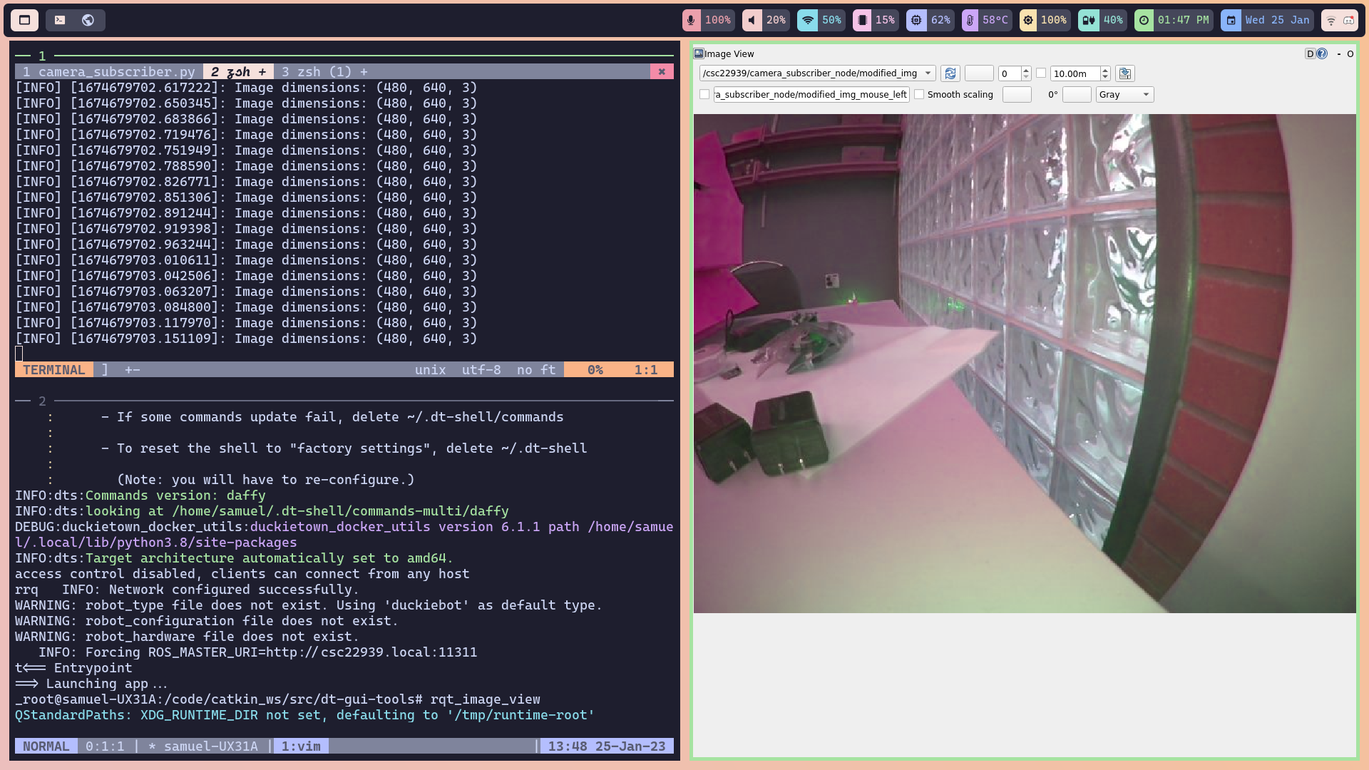 Figure 5: Using
 rqt_image_view to display the images sent on the modified camera topic we implemented in our CameraSubscriberNode class. Here, I’ve switched the blue and green channels to create a GBR image.
Bonus: Flashing SD Card Fails… Yet Another Challenge in Completing this Lab
While trying to complete this lab, my DuckieBot started using nearly 100% of its RAM, which meant I could no longer build any programs on it. Unfortunately, I couldn’t figure out what caused this issue, so I had to reflash the SD card on my DuckieBot.
To my suprise, the reflash didn’t work. I kept getting a KeyError saying that 1.2.2 was not a key in the board_to_placeholders_version dictionary, and the DuckieBot could not boot from the SD card. This was quite a difficult issue to solve. After hours of debugging and diving into the source code for init_sd_card, I found that a recent commit had broken this command. The placeholders_version should have been set to 1.2.2, but the commit had changed that to 1.2.1. Updating this line of code fixed the problem! We added a comment to the commit, which has now been fixed.
What Did I Learn/Conclusions
This exercise taught me a few things:
- I love simulation. It’s much easier to get a simulator to work than it is to get a real-life robot to work.
- DuckieTown needs more documentation.
- Dive into the source code. DuckieTown is lacking documentation, and the source code is the next best resource.
- Odometry: before this exercise, I had no idea what odometry even was!
- Odometry is inaccurate! After driving the DuckieBot for a short amount of time, the odometry estimation is quite different from where the DuckieBot is in the real world. We need more than just odometry to figure out where our DuckieBot really is.
- DuckieTown should be maintained better. We shouldn’t have to adjust the source code of commands to simply get our DuckieBot working.
References
[3] Matplotlib Animate Library Documentation. Link.
[4] DuckieTown Lane Following Demo. Link.
[6] Introduction to Autonomous Mobile Robots: First Edition. R. Siegwart and I. Nourbakhsh. MIT Press. 2004. Link.
[7] Hands-on Robotics Development using Duckietown: Odometry with Wheel Enocders. Link.