This post is the third part of the Robotics/DuckieTown series.
All code in this lab is heavily taken and adapted from the duckietown demos found in
dt-core. Since this is documented in all the READMEs and in this prompt, I haven’t included any citations in the Python files themselves. It should be clear that these files come from thedt-corepackage.
See my github repository for the code in this document.
Introduction
If you’ve been following along with this series, you’ve now successfully built your Duckiebot and performed some simple open-loop control with the robot. You probably also experienced the difficulty of open-loop control. It’s hard to correct for your actions if you can’t observe their consequences!
Here, we’re going to be discussing localization with sensor fusion and closed-loop control. Closed-loop control means that we can control our bot, look at its sensors, and then make decisions about how to control our robot based on its sensor readings. Localization is trying to figure out where you are, and sensor fusion roughly means using a bunch of sensors to be able to better localize.
In the previous post, you probably saw how odometry was inaccurate. We need something better than odometry to figure out where our robot is in the real world. In this post, we’re going to be using odometry, but correcting it with apriltags. We’ll use odometry to figure out where our robot is, but when we see an apriltag (and assuming we know in the real world where that apriltag exactly is, we can use that to correct our odometry).
This post has roughly three parts. First, we’re going to discuss apriltags and how we can get our robot to recognize them. Second, we’ll discuss lane following. Finally, we’ll discuss how we can use apriltags to figure out where we are in the real world and correct the errors in our odometry. Because there is so much to discuss and to code in this post, we’ll be heavily taking and adapting code from dt-core.
Apriltags
Apriltags are similar to QR codes, but encode smaller amounts of data. They are going to be the main method by which we recognize signs in Duckietown. We are going to be using tag36h11 apriltags. See this reference if you’re interested to learn more about apriltags.
Basic Augmented Reality Exercise
Our first task is to get familiar with augmented reality in Duckietown. We’ll follow this page, stopping at Unit A-3. Go ahead and read over the first two units, that’s all there is to those parts. No coding required.
For Unit A-3, we simply want to draw segments on an image produced by the Duckiebot camera. The segments are defined in yaml files on the webpage for Unit A-3. I won’t go into detail on how to complete this part, but my solution to it can be found in my Github repo under ./Code/Lab3/Part1/packages/augment_reality_basics. You should be able to copy that code and run it on your Duckiebot, but make sure to save the calibration files to /data/map on your bot before running the code. You can choose the calibration file to use using the map_file command argument, specified either on the command line or in the launch file. I’ve specified it as a command line argument in the ./launchers/default.sh file:
1
dt-exec roslaunch augmented_reality_basics nodes.launch veh:=$VEHICLE_NAME map_file:="/data/map/calibration_pattern.yaml"
Challenges
One of the big challenges I faced in completing this section was inaccurate documentation. When trying to project segments to the ground plane, I was using the ground2pixel function from the ground_projection package. The documentation for this function was incorrectly copied from the ground2vector function in the same package.
Apriltag Detection
In order to localize where the robot is using apriltags, we need to first be able to recognize and detect apriltags. In this section, we’re going to write a node that will:
- Subscribe to the camera topic
- Undistort the image using our camera calibration
- Detect apriltags and publish images to a new topic with a bounding box around the apriltag and a label under the apriltag
- Change the LED lights on the Duckiebot based on the apriltag it saw last:
- Set the LED colour to be red for stop signs
- Set the LED colour to be blue for T-intersections (right-T-instersections, left-t-intersections, and T-intersections)
- Set the LED colour to be green for the UofA tag (4-way-intersections)
- Set the LED colour to be white when no tag is detected
To implement this, we’re going to heavily rely on the apriltag package from dt-core. Go grab that code now, you’ll need the entire apriltag package.
Now, this code is going to automatically detect, label, and draw a bounding box around apriltags for us! How great! In particular, the apriltag_detector_node will detect these apriltags and send images of the labelled apriltags on the ~apriltag_detector_node/detections/image topic. Furthermore, this node will send metadata about the apriltags along the ~apriltag_detector_node/detections topic in the form of AprilTagDetectionArray messages, which is just a message which holds a list of AprilTagDetection messages.
If you’re interested to learn more about how apriltag detection works, the code in
dt-coreuses the dt-apriltag library to detect apriltags.
We still need to do a bit of work to finish this part of the assignment. If you have updated your DB21 Duckiebot to the latest version, you may no longer have access to the led_emitter node, which means that we can’t change the colours of the LEDs. If this is the case, you can grab this node from here. Be sure that you launch this node before continuing. You can do so by adding the following code to ./launchers/default.sh:
1
dt-exec roslaunch led_emitter led_emitter_node.launch veh:=$VEHICLE_NAME
Now, we’re ready to start changing the LEDs of the Duckiebot based on apriltags. We have the metadata about apriltags being send on the ~apriltag_detector_node/detections topic. The apriltag_postprocessing_node (in the apriltag_postprocessing_node.py file) already does some postprocessing of apriltags using this topic, so we’ll add some code to this node to change the LEDs of the Duckiebot based on the apriltag in view. Let’s start by connecting to the LED changing service. Add the following line of code to the apriltag_postprocessing_node constructor:
1
2
3
4
# Service for changing LED colours
self._led_svc = rospy.ServiceProxy(
    "led_emitter_node/set_pattern", ChangePattern,
)
You might have to remap the service name in your launch file to reflect the correct service running on your Duckiebot (likely, it will be called ROBOT_NAME/led_emitter_node/set_pattern). Next, add a method to the class which will switch the LED colours:
1
2
3
4
5
6
7
8
9
10
11
12
13
14
15
16
17
18
19
20
21
def _switch_led(self, id_info):
    sign = self.traffic_sign_types[id_info["traffic_sign_type"]]
    sign_types = self.traffic_sign_types
    t_intersect_signs = set(
        (
            sign_types["right-T-intersect"],
            sign_types["left-T-intersect"],
            sign_types["T-intersection"],
        )
    )

    if sign == sign_types["stop"]:
        self._led_svc(String("RED"))
    elif sign in t_intersect_signs:
        self._led_svc(String("BLUE"))
    elif sign == sign_types["4-way-intersect"]:
        self._led_svc(String("GREEN"))
    elif sign is sign_types[None]:  # None
        self._led_svc(String("WHITE"))
    else:
        raise RuntimeError(f"unknown traffic sign {sign}")
Here, I’ve set the default colour of the LEDs to white, so they will be white if no apriltag is detected. For this to work, you need to add the key-value pair None: None to the self.traffic_sign_types instance variable of the apriltag_postprocessing_node class. Now, it’s fairly simple to get the LED colours to change. In the method callback for the apriltag_postprocessing_node (line 118 if you’re following along with my repo), you’ll see the following line:
1
2
for detection in msg.detections:
    # ...
This for loop does a bunch of postprocessing of apriltags that might be useful later, so we’ll leave it be. But, we can add to this method to change the LED colours of the Duckiebot based on the apriltag. To do so, we’re going to use the not-so-well-known for-else statement in Python. How this works is the following. You have a regular for loop, and if that for loop finishes normally without a break, then the code in the else block gets run. If you break out of the for loop, the code in the else block does not get run. For example, the following will print “done”:
1
2
3
4
for i in range(3):
    pass
else:
    print("done")
but the following will not print “done”:
1
2
3
4
5
for i in range(3):
    if i == 2:
        break
else:
    print("done")
Okay, so now that we know about for-else statements, let’s use one! Modify the callback method in the apriltag_postprocessing_node class, to look like the following:
1
2
3
4
5
6
7
8
9
10
11
12
13
14
15
16
17
18
19
20
21
22
23
24
25
def callback(self, msg):
    tag_infos = []

    new_tag_data = AprilTagsWithInfos()

    id_info = {
        'tag_id': None,
        'tag_type': None,
        'street_name': None,
        'vehicle_name': None,
        'traffic_sign_type': None,
    }

    # Load tag detections message
    for detection in msg.detections:
        # leave this block of code as is it defines `id_info` needed in the
        # proceeding `else` statement
    else:
        # Update the LED colour
        self._switch_led(id_info)

    new_tag_data.infos = tag_infos

    # Publish Message
    self.pub_postPros.publish(new_tag_data)
The only thing that should be changed is the additoin of the else statement after the for loop. Now, whenever the for loop runs, it will define a variable id_info, which provides info about the currently viewed apriltag. If the loop finishes running normally (in which case id_info is guaranteed to exist), then we will changed the LED colour based on this id_info variable.
That’s all there is to it! You can view my implementation on my Github repo (link above). Below, you can see a video of this code in action. I’ve placed the Duckiebot beside my computer and am displaying the images from the ROBOT_NAME/apriltag_detector_node/detections/image topic using rqt_image_view. As I change the apriltag, the image updates to label the apriltag with the corresponding apriltag ID, and the LEDs on the Duckiebot change to the proper colour.
As you can see, the program recognizes and labels apriltags fairly efficiently.
The dt-apriltags Library
If you looked at the tip above, you would have been directed to the dt-apriltags library, which is the library that is used to detect apriltags in our code here. The main function to consider in this library is the detect function, which will detect an apriltag in an image and provide valuable information about the apriltag in a Detection object.
To determine the position of an apriltag, the Detection object has two fields pose_R and pose_t which will tell you the rotation and translation of the apriltag in the camera frame [1, 2], outlined in Figure 1. In this frame, z-values increase forward (out from the camera), x-values increase going to the left (when viewing the camera head-on) and y-values increase downwards. This is similar to the frame used with apriltags, outlined in Figure 1 as well. In this frame, z-values increase going out of the apriltag’s back, x-values increase to the right of the apriltag (when viewing the apriltag head-on), and y-values increase downwards from the apriltag. Both the camera and apriltag use the right-hand-rule for frame orientation. The Detection object also provides other fields such as the corners of the apriltag in pixel space and the apriltag homography matrix for projecting the apriltag to pixel space.
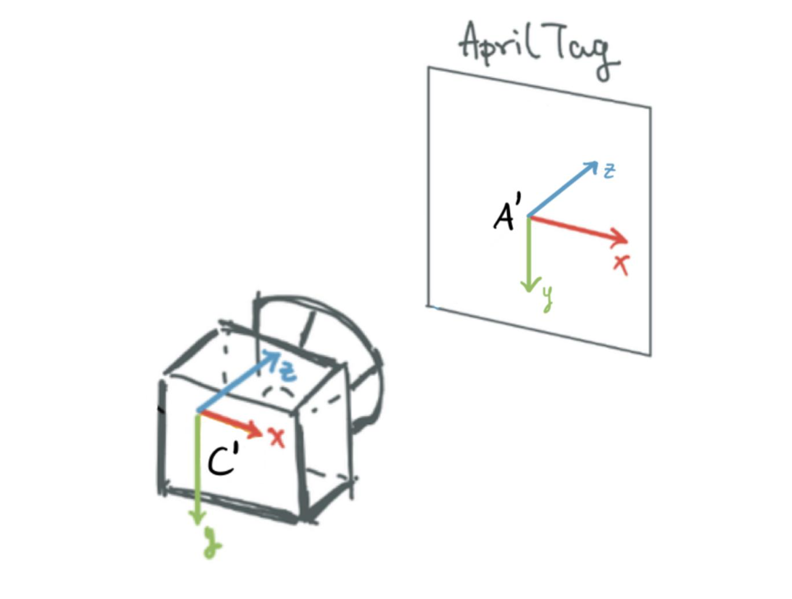 Figure 1: Axes in the camera and apriltag frames, as returned by the
 dt-apriltag package. Red denotes the x-axis. Green denotes the y-axis. Blue denotes the z-axis. Image taken from here.
Eventually, we will need to get our camera frame looking like that in Figure 2, which is what the Duckiebot expects and is quite different from the camera frame used by dt-apriltags. Luckily, this is easy with the tf2_ros package, since Duckietown provides us with the transformations needed to go from the dt-apriltags camera frame to the one in Figure 2. Likely, you won’t have to do any coding to get this to work, but can just immediately work with the tf2_ros library (more on this later).
 Figure 2: Axes in the camera frame used by the Duckiebots. Red denotes the x-axis. Green denotes the y-axis. Blue denotes the z-axis. Image taken from here.
On our Duckiebots, the camera frame that the
dt-apriltagslibrary uses (see Figure 1) is called~camera_optical_frameand the camera frame expected by our Duckiebots is called~camera_frame(see Figure 2). Duckietown provides code to automatically transform between these frames intfandtf2_ros. You can visualize how these frames are connected by usingview_framesto plot the transform graph.
Special Considerations when Localizing with Apriltags
Finally, there are two things to consider when detecting these apriltags. First, you may not want to detect apriltags from far away, as this will increase the error of apriltag detection. The reason is that as an apriltag gets farther away, it’s more difficult to tell two apriltags apart. Not only does this happen for our Duckiebot, but it would also happen to you as well. You might be able to tell the differences between two apriltags if they’re a metre in front of you, but if they are a kilometre away from you, you probably won’t be able to tell two apriltags apart very easily.
Second, we should likely limit the rate of apriltag detection. This is because, to detect an apriltag, we need to process a large image (this is expensive), copy it, augment it, and then send the augmented image (with a bunch of metadata) along two other topics. Because the images are large data structures, if we process and send many images per second, we may put too much load on our Duckiebot and slow the whole thing down.
Furthermore, our final goal is to use apriltags to help localize. Remember that errors in odometry accumulate over time. Once we correct the errors in odometry using landmarks such as apriltags, there should be little error left in our odometry estimate. Hence, there’s no point in correcting our odometry estimate again using the apriltags. We should wait for a while until errors build up in our odometry before using apriltags to correct our odometry again.
Lane Following
Next, we’re going to implement lane following, and as a bonus, lane following in the English driving style (i.e. on the wrong left side of the road)! As in the previous section, we’re going to rely on code implemented in dt-core and adapt it to fit our needs.
Adapting this code to fit our needs is actually difficult since so much goes into the dt-core implementation of autonomous lane following. In the Apriltags section above, we could simply grab one package and adapt that package to our needs, but that’s not the case here. Therefore, I won’t go through the details of how I stripped down their lane following demo to fit our needs (this was quite the challenge and took a significant amount of time; you have to understand the code thoroughly). Instead, feel free to grab the stripped down lane following code from my Github repository.
The lane following package in dt-core already had a PI(D) controller (i.e. a PID controller without the D term) for lane following; I adapted that to be a full PID controller. I also implemented the English driving style. Let’s go through the details of how I did each of these, but first, it might help to review what exactly each package does.
Overview of the Lane Following Package
The following sections provide a very brief overview of the most important packages for lane following.
ground_projection
The ground_projection package projects the line segments detected in the image to the ground plane in the robot’s reference frame.
image_processing
The image_processing package takes care of preprocessing images from the Duckiebot camera before any other nodes access these images. For example, this package will ensure camera images are rectified before any other package uses the images. Furthermore, this package broadcasts images along the well-known ~image/compressed topic.
lab3
Contains the launch files for the lane following code.
lane_control
The lane_control package implements a PID controller to control the Duckiebot to lane follow. We use two errors for the PID controller, the heading deviation and the lateral deviation of the Duckiebot from the target position. By default the target position is the lane centre, but we can adjust this (discussed later). These errors are acquired from the lane pose published by the lane_filter_node in the lane_filter package.
lane_filter
The lane_filter package reads lines from the line_detector package to determine the Duckiebot’s lane pose, which includes its offset from the centre of the lane (lateral deviation from the lane centre) and its orientation from facing straight down the lane (heading deviation from the lane centre).
The lane_filter uses a Histogram Grid Filter to estimate the lane pose of the Duckiebot.
One way to implement the English driving style is to offset the centre of the lane in this package as done in [3].
led_emitter
The led_emitter package takes care of adjusting the LEDs on the Duckiebot.
line_detector
The line_detector package detects lines to be used to filter lanes in the lane_filter package.
Adapting the PI(D) Controller to be a PID Controller
The PID controller which I implemented for lane following (adapted from that in dt-core) can be found in the lane_control package under include/lane_controller/controller.py. The single class in this file LaneController implements the PID logic and is a helper class for the node which implements lane control, found under src/lane_controller_node.py.
In the LaneController class, the most important method is the compute_control_action method and has the following signature:
1
2
3
def compute_control_action(
    self, d_err, phi_err, dt, wheels_cmd_exec, stop_line_distance, current_lane_pose,
):
This method takes in two different errors, the lateral deviation d_err and the heading deviation phi_err. The dt parameter is the time since the last control action was computed; the wheels_cmd_exec parameter serves as confirmation that the wheel commands have been executed (this is used for the integration term); the stop_line_distance is used for stopping at stop lines (we don’t use this in this exercise, but I’ve included it to make adding the stop line package later easier). Finally, the current_lane_pose is the estimated current lane pose of the Duckiebot and is used in the derivative term of the PID controller. This is the only extra parameter I added to this method when compared to the dt-core implementation (since we need this term for estimating the derivative of the error).
Implementing the Derivative Term in PID
To implement the derivative term for this PID controller, I had to make a number of changes. First, I added a method to the class to calculate the derivative of the error terms:
1
2
3
4
5
6
7
8
9
10
11
12
13
14
15
16
17
18
19
20
21
22
23
24
25
26
27
28
29
def differentiate_errors(self, d_err, phi_err, dt, current_lane_pose=None):
    """
    Differentiates error signals in lateral and heading direction.

    Args:
        d_err (:obj:`float`): error in meters in the lateral direction
        phi_err (:obj:`float`): error in radians in the heading direction
        dt (:obj:`float`): time delay in seconds
        current_lane_pose (:obj:`duckietown_msgs.msg.LanePose`): the
            current pose in the lane
    """
    if not self._derivative_initialized:
        # First time step, no derivative to calculate
        return

    if self.parameters["~deriv_type"] == "value":
        # Calculate the derivative based on values (as negative velocity)
        self.d_D = (current_lane_pose.d - self.prev_lane_pose.d) / dt
        self.phi_D = (current_lane_pose.phi - self.prev_lane_pose.phi) / dt

    elif self.parameters["~deriv_type"] == "error":
        # Calculate the derivative based on errors
        self.d_D = (d_err - self.prev_d_err) / dt
        self.phi_D = (phi_err - self.prev_phi_err) / dt
    else:
        deriv_type = self.parameters["~deriv_type"]
        raise NotImplementedError(
            f"deriv_type {deriv_type} not implemented",
        )
One thing you might notice is that the derivative has the wrong sign, it’s applying a force in the same direction as the Duckiebot’s movement, meaning that the derivative is acting as an accelerating force, rather than as a breaking force. To correct this, we simply will use a negative coefficient for the derivative term once we tune the PID controller. This is also what dt-core does for the proportional and integral terms of the PID controller, and I’ve done it this way for consistency.
You’ll also notice that in the implementation above, we can compute the derivative using errors or using velocities.
There’s a few things we need to add to the constructor now. To be able to calculate the derivative using errors, we need to store the errors at the last time step. We also need a flag to tell if the derivative has been initialized or not (on the first step, we can’t compute the derivative since we don’t have an error/veloctiy from the previous time step). Let’s add these to the class constructor, which should now look like this:
1
2
3
4
5
6
7
8
9
10
11
def __init__(self, parameters):
    self.parameters = parameters
    self.d_D = 0.0
    self.d_I = 0.0
    self.phi_I = 0.0
    self.phi_D = 0.0

    # Add these three fields
    self.prev_d_err = 0.0
    self.prev_phi_err = 0.0
    self._derivative_initialized = False
For the final step, we need to use the derivative term when calculating the control action in our PID control logic. To do so, we simply need to update the compute_control_action to use the differentiate_errors function we just defined:
1
2
3
4
5
6
7
8
9
10
11
12
13
14
15
16
17
18
19
20
21
22
23
24
25
26
27
28
29
30
31
32
33
34
35
36
37
38
39
40
41
42
43
44
45
46
47
48
49
50
51
52
53
54
55
56
57
58
59
60
61
62
63
64
65
66
67
68
def compute_control_action(self, d_err, phi_err, dt, wheels_cmd_exec,
                           stop_line_distance, current_lane_pose):
    """Main function, computes the control action given the current error signals.

    Given an estimate of the error, computes a control action (tuple of linear
    and angular velocity). This is done via a basic PID controller with
    anti-reset windup logic.

    Args:
        d_err (:obj:`float`): error in meters in the lateral direction
        phi_err (:obj:`float`): error in radians in the heading direction
        dt (:obj:`float`): time since last command update
        wheels_cmd_exec (:obj:`bool`): confirmation that the wheel commands
            have been executed (to avoid integration while the robot does not move)
        stop_line_distance (:obj:`float`):  distance of the stop line, None if
            not detected.
        current_lane_pose (:obj:`Pose`):  current pose
    Returns:
        v (:obj:`float`): requested linear velocity in meters/second
        omega (:obj:`float`): requested angular velocity in radians/second
    """

    if dt is not None:
        self.integrate_errors(d_err, phi_err, dt)
        self.differentiate_errors(
            d_err, phi_err, dt, current_lane_pose=current_lane_pose,
        )

    self.d_I = self.adjust_integral(
        d_err,
        self.d_I,
        self.parameters["~integral_bounds"]["d"],
        self.parameters["~d_resolution"]
    )
    self.phi_I = self.adjust_integral(
        phi_err,
        self.phi_I,
        self.parameters["~integral_bounds"]["phi"],
        self.parameters["~phi_resolution"],
    )

    self.reset_if_needed(d_err, phi_err, wheels_cmd_exec)

    if self._derivative_initialized:
        omega = (
            self.parameters["~k_d"].value * d_err
            + self.parameters["~k_theta"].value * phi_err
            + self.parameters["~k_Id"].value * self.d_I
            + self.parameters["~k_Iphi"].value * self.phi_I
            + self.parameters["~k_Dd"].value * self.d_D
            + self.parameters["~k_Dphi"].value * self.phi_D
        )
    else:
        omega = (
            self.parameters["~k_d"].value * d_err
            + self.parameters["~k_theta"].value * phi_err
            + self.parameters["~k_Id"].value * self.d_I
            + self.parameters["~k_Iphi"].value * self.phi_I
        )
        self._derivative_initialized = True

    self.prev_d_err = d_err
    self.prev_phi_err = phi_err
    self.prev_lane_pose = current_lane_pose

    v = self.compute_velocity(stop_line_distance)

    return v, omega
On lines 44 - 60 of the previous code snippet, you’ll see a few terms of the form self.parameters["PARAM"].value. These are the P, I, and D coefficients for the PID controller. They weight how much each of the P, I, and D terms contribute to the overall computed control action. For example, the variable self.parameters["~k_d"].value weights how much the lateral deviation error should contribute to the control action. Remember when I previously said that the derivative term has the wrong side? Well, these terms are how we fix that, and all of them should be negative to ensure the P, I, and D terms in the PID controller have the correct sign.
Oh, we should also be sure the reset the derivative term if the Duckiebot ever stops moving. To do so, we’ll simply update the reset_if_needed method:
1
2
3
4
5
6
7
8
9
10
11
def reset_if_needed(self, d_err, phi_err, wheels_cmd_exec):
    if np.sign(d_err) != np.sign(self.prev_d_err):
        self.d_I = 0
    if np.sign(phi_err) != np.sign(self.prev_phi_err):
        self.phi_I = 0
    if wheels_cmd_exec[0] == 0 and wheels_cmd_exec[1] == 0:
        self.d_I = 0
        self.phi_I = 0

        # Add the following line
        self._derivative_initialized = False
Setting and Tuning the PID Coefficients
There are just a few more changes that we need to make in the src/lane_controller_node.py file before we can set and tune the coefficients for the PID controller. This file holds the full lane controller node. In this file, we should update the calls to compute_control_action to also take the current lane pose (which we added for calculating the derivative term). Finally, we should add a few more parameters in the LaneControllerNode constructor:
1
2
3
4
5
6
7
self.params["~k_Dd"] = DTParam(
    "~k_Dd", param_type=ParamType.FLOAT, min_value=-100.0, max_value=100.0,
)
self.params["~k_Dphi"] = DTParam(
    "~k_Dphi", param_type=ParamType.FLOAT, min_value=-100.0, max_value=100.0
)
self.params["~deriv_type"] = rospy.get_param("~deriv_type", "error")
Alright, now our changes to the lane following controller are complete! Let’s set the PID coefficients now! These coefficients are stored as ROS params, and we can set them in the packages/lane_control/config/lane_controller_node/default.yaml file:
1
2
3
4
5
6
7
8
9
10
11
12
13
14
15
16
17
v_bar: 0.19     # Speed of Duckiebot

k_d: -6.0       # Coefficient for P term (lateral deviation); should be <= 0
k_Id: -0.3      # Coefficient for I term (lateral deviation); should be <= 0
k_Dd: -0.3      # Coefficient for D term (lateral deviation); should be <= 0

k_theta: -5.0   # Coefficient for P term (heading deviation); should be <= 0
k_Iphi: -0.0    # Coefficient for I term (heading deviation); should be <= 0
k_Dphi: -0.0    # Coefficient for D term (heading deviation); should be <= 0

theta_thres: 0.523  # Maximum heading deviation error
d_thres: 0.2615     # Maximum lateral deviation error

d_offset: 0.0       # Offset of target for lateral deviation from lane centre

deriv_type: "value" # How to compute derivatives, one of 'value', 'error'
# ...
You can set each of these parameters and then build and run the lane following package (in the Code/Lab3/Part2 directory in my Github repo) on your Duckiebot to see how they affect lane following.
One nice part of our implementation is that since we used DTParam objects for these parameters, we can adapt the parameters while the program runs on the Duckiebot. We don’t have to build and run each time we change the parameters! To do so, first build and run the program on your Duckiebot. Then, to dynamically set parameter PARAM to value VALUE, you can simply run:
1
$ rosparam set /ROBOT_NAME/lane_controller_node/PARAM VALUE
on the command line. Try playing around with all these settings until you find a good combination (i.e. the Duckiebot can lane follow accurately). I found that the above parameters worked nicely on my Duckiebot, but they might not be the best for your robot.
Challenges
One challenge I faced when trying to get the lane following demo to work was that after I had made all the changes described above, the robot would still not move. After some detective work, I figured out why.
To get the Duckiebot to drive like a car, you need to publish Twist2DStamped messages to the /ROBOT_NAME/car_cmd_switch_node/cmd topic. The LaneControllerNode publishes Twist2DStamped controls to the /ROBOT_NAME/lane_controller_node/car_cmd topic.
When you have the entirety of the Duckietown lane following demo implemented (stop lines, traffic lights, obstacle avoidance, etc.), a special node called the fsm_node will actually take the messages from the /ROBOT_NAME/lane_controller_node/car_cmd and transfer them to the /ROBOT_NAME/car_cmd_switch_node/cmd topic for us. But, we aren’t using the full Duckietown lane following demo. Instead, we just use the lane following part (we don’t use stop lines, obstacle avoidance, etc.). In this case, we have no need for the fsm_node, and so I had removed it.
To deal with this, I simply remapped the topic along which the LaneControllerNode sends commands to be the correct one: /ROBOT_NAME/car_cmd_switch_node/cmd. After I did that, the lane following worked great! It did take quite a bit of detective work to figure this out though.
Implementing English Driving Style
Now that we have our lane following code working, implementing the English driving style is actually quite simple! Right now, our Duckiebot drives on the correct right side of the road. There are two ways to get it to drive on the wrong left side of the road: we can use the lane_filter package or the lane_control package. I implemented both methods, but found that implementing the English driving style in the lane_control package resulted in better accuracy than implementing it in the lane_filter package. Because of this, I won’t discuss my implementation of the English driving style in the lane_filter package.
To see how I implemented the English driving style using the
lane_filterpackage, see my Github repo. You can do a diff of my implementation with that indt-coreto see what I changed.
I used [3, 4] to implement the English driving style in the
lane_filterpackage. You can also check out these resources.
To implement the English driving style using the lane_control package, all we need to do is set the ~d_offset parameter in the packages/lane_control/config/lane_controller_node/default.yaml file. You should set this value to be the distance (in metres) between the centre of the right and left lanes (~0.2 in my case). That’s it! You’re done! You might need to re-tune the PID controller parameters as well.
A Note on the Performance using the English Driving Style
When attempting to use the English driving style in this way, you might notice that it’s a lot more inaccurate than driving in the American style. Why is that?
Well, this code always looks at the right-hand lane to figure out the lateral and heading deviation and then offsets by ~d_offset if needed. In the American driving style, ~d_offset = 0, and the right hand lane is in full view.
In the English driving style (~d_offset != 0), the Duckiebot is in the left-hand lane but still tries to make decisions based on the lateral and heading deviation in the right-hand lane (this is what the ~d_offset parameter does). The issue is that when the Duckiebot is in the left-hand lane, the right-hand lane may not be in full view and is compressed and warped in the camera image (instead of being in the centre of the camera image, the right-hand lane will be pushed to the right-hand side of the image). This makes determining the lateral and heading deviation of the Duckiebot much more difficult and results in worse performance compared to the American driving style. This is like if you tried to drive in the right-hand lane in real life but could only see the left-hand lane. You’d probably be bad at it too!
The video below shows the Duckiebot autonomously driving in the English style using this method:
You might notice that the Duckiebot drives over the yellow line a bit. We could address this by increasing the offset, but the more you increase the offset, the worse the performance gets because of the aforementioned issues. I think this performance is quite good in any case!
A Few Questions
There’s a few questions we should go over as review:
- Q: What is the error we used for the PID controller?
A: We used two errors to compute control actions, the lateral deviation and heading deviation from the lane centre.
- Q: If your proportional controller did not work well alone, what could have caused this?
- A: The proportional controller works in the following way: compute the lateral and heading deviations from the centre of the lane and turn the Duckiebot proportionally to each of these errors. A few reasons why this might not work well alone, without the I and D terms:
- If the errors are very large, what could happen is the Duckiebot could move almost horizontally in the lane, and could then lose track of the lane in the camera.
- Using just a proportional controller could also cause the Duckiebot to zig-zag around centre of the lane. This is because, when the Duckiebot is not centred in the lane, it will attempt to drive toward to centre of the lane proportionally to how far away it is from the lane’s centre. Once the Duckiebot gets to the lane centre, the error becomes 0, but the bot is still driving at an angle. Because the error is 0, the Duckiebot cannot correct its angle to drive straight down the lane (it can only correct proportionally to the error, which is 0). Instead, it will continue driving with an angle until it drives past the centre of the lane. Once it does so, the error will become non-zero again and the Duckiebot will change its direction and try to approach the centre of the lane, starting the entire process once again. Since our implementation also includes a heading deviation error term, this zig-zagging will actually be somewhat mitigated but nevertheless will still have some effect.
I noticed that if you only use a proportional controller, this zig-zagging is quite bad when the lane turns. This is because the centre of the lane is changing (turning) during a lane turn and the Duckiebot must constantly correct for the changing target (lane centre).
- Q: Does the D term help your controller logic? Why or why not?
- A: The D term does help the controller logic. It reduces the zig-zagging nature of the P controller (during straight portions of the lane) by acting as a braking force, allowing the Duckiebot to smoothly approach the lane centre. Furthermore, if the errors are large, the D term improves the controller by ensuring that the Duckiebot slowly adjusts its position in the lane, rather than making a quick turn to get to the lane centre.
- Q: Why or why not was the I term useful for your robot?
- A: I noticed that the I term was especially useful during lane turns. I believe this is because the target (lane centre) changes (turns) during the lane turn. With the PD controller, the robot will constantly make corrections during the turn to account for the changing lane centre. The I term allows us to take all of these small changes into account and integrate over them to ensure the Duckiebot turns smoothly.
Localization using Sensor Fusion
In this section, we talk about fusing sensors to better localize (i.e. using odometry and apriltags for localization). In particular, we’re going to localize with apriltags when we see one, and odometry when we don’t see any apriltags.
This is a big section, and because of it I won’t go into detail on the code I implemented. Instead, you can take a look at the code in Code/Lab3/Part3 in my Github repo if you would like to see more. We’re going to start with this code template and then implement all the required functionality (the final product is on my GitHub repo).
But before we jump into the assignment and implementation, we need to get one thing out of the way: the coordinate system of Duckietown (i.e. the world frame). Figure 3 shows the Duckietown setup I’m working with, along with the coordinate system in use. The origin is at the bottom left hand side of Duckietown, and we use the right-hand-rule for the Duckietown world frame. The y-axis increases upwards in the image, and the x-axis increases to the right in the image. The z-axis increases out of the image plane (imagine the z-axis coming out of your screen towards you).
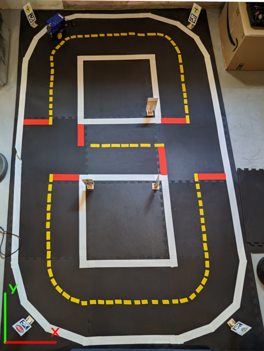 Figure 3: The Duckietown coordinate system with the origin on the bottom left of Duckietown. We use the right-hand-rule for the coordinate system of Duckietown. The y-axis (green) increases upwards in the image. The x-axis (red) increases rightwards in the image. The z-axis increases out of the image plane, extending out of the screen towards you.
Odometry Frame
In this section, we want to modify the deadreckoning node (odometry) from the code template to visualize the Duckiebot’s position in RViz. First, we want to set the parent and child frames of the odometry package to be “world” and “odometry” respectively.
To do this, I first renamed the fields self.origin_frame to self.parent_frame and self.target_frame to self.child_frame in the DeadreckoningNode node in the deadreckoning_node.py file. Then, to set the parent and child frame, simply change the file packages/deadreckoning_node/config/deadreckoning_node/default.yaml from:
1
2
3
4
5
6
# ...
# origin reference frame name
origin_frame: "~/odom"
# target reference frame name
target_frame: "~/base_footprint"
# ...
to
1
2
3
4
5
6
# ...
# parent reference frame name
parent_frame: "world"
# child reference frame name
child_frame: "odometry"
# ...
The DeadreckoningNode already takes care of broadcasting the transform from the world frame to the odometry frame using tf2, so this is all you need to do for this section.
Now that we have this, we can open RViz by first starting the gui tools from dts and then running the rviz command. Once RViz opens, you can set the fixed frame to be “world”, add an image visualization, and add a TF visualization. Using the keyboard controls, you can move your Duckiebot. You should see the odometry frame moving in RViz as you drive your bot.
I also added parameters to the
deadreckoning_nodeconfig file for setting the start position and rotation of the Duckiebot (and made appropriate changes in theDeadreckoningNodecode as well).
Creating Static Landmark Frames
A useful resource for this section is [7].
Our final goal is to use use apriltags to localize when possible and odometry otherwise. To reach this goal, we need to know where the apriltags are in the real world. You can place some apriltags around your Duckietown wherever you’d like. I’ve placed mine at each of the 4 corners of Duckietown. Then, you should measure the position (in metres) of each apriltag in Duckietown and make note of its rotation.
We can then add static landmark frames by adding these nodes to the launch files. The general syntax for creating a static landmark frame is:
1
<node pkg="tf2_ros" type="static_transform_publisher" name="NODE_NAME" args="XPOS YPOS ZPOS ROLL PITCH YAW PARENT_FRAME CHILD_FRAME" />
where NODE_NAME is the name of the node which holds the static landmark frame, and args should be self-explanatory. I’ve added the following static landmark frames to my Duckietown:
1
2
3
4
5
6
7
<node pkg="tf2_ros" type="static_transform_publisher" name="at_22_static" args="0.17 0.20 0 2.35 0 -1.57 world at_fixed_22" />
<node pkg="tf2_ros" type="static_transform_publisher" name="at_8_static" args="1.58 0.17 0 3.93 0 -1.57 world at_fixed_8" />
<node pkg="tf2_ros" type="static_transform_publisher" name="at_63_static" args="0.215 2.815 0 0.785 0 -1.57 world at_fixed_63" />
<node pkg="tf2_ros" type="static_transform_publisher" name="at_67_static" args="1.65 2.755 0 -0.785 0 -1.57 world at_fixed_67" />
<node pkg="tf2_ros" type="static_transform_publisher" name="at_76_static" args="0.66 1.17 0 0 0 -1.57 world at_fixed_76" />
<node pkg="tf2_ros" type="static_transform_publisher" name="at_15_static" args="1.17 1.17 0 -1.57 0 -1.57 world at_fixed_15" />
<node pkg="tf2_ros" type="static_transform_publisher" name="at_59_static" args="1.17 1.83 0 3.142 0 -1.57 world at_fixed_59" />
You can then visualize these frames in RViz using TF visualizations. Use these visualizations to ensure you got the position and rotation of each apriltag correct.
Next, we want to update our deadreckoning node to use a topic to update its x, y, z, and theta fields (these are the estimates of the Duckiebot’s position and orientation in the world frame, currently gotten through odometry). When a message comes along this topic, the deadreckoning node will update its current odometry estimates (this topic is how we will later update oru localization using apriltags). To do so, I simply added this to the DeadreckoningNode constructor:
1
self.sub_odom_update = rospy.Subscriber("~update_odom", Pose, self.update_odometry)
and added the following method to the DeadreckoningNode:
1
2
3
4
5
6
7
8
9
10
11
12
13
14
15
def update_odometry(self, pose: Pose):
    self.x = pose.position.x
    self.y = pose.position.y
    self.z = pose.position.z

    q = [
            pose.orientation.x,
            pose.orientation.y,
            pose.orientation.z,
            pose.orientation.w,
    ]

    yaw = tr.euler_from_quaternion(q)[2]

    self.yaw = yaw
In the video below, I start up RViz and visualize the Duckiebot’s odometry frame as well as a few of the apriltag static landmark frames. I first update the Duckiebot’s initial position using the topic we just added, then drive around in a circle to get an idea of where the odometry accumulates errors most:
As you can see in the video, the odometry drifted most when rotating the Duckiebot. It’s well-known that odometry accumulates error very rapidly with wheeled mobile robots when turning, much more rapidly than when driving straight. This might be because, when turning, one wheel has to rotate very fast, and fast movements increase the errors in odometry significantly. Furthermore, you’ll notice that at the beginning of the video, the Duckiebot thought we were driving diagonally when really we were driving straight forward. This is because there was a slight rotation right at the beginning as soon as I started driving which affected the odometry estimation.
If you didn’t have the apriltags frames (or any other landmarks) in RViz, it would be quite difficult to tell when and where the odometry estimates drifted most. With the apriltags, it’s much easier to see where exactly the odometry accumulated its errors. This makes sense! Without the landmarks, comparing the Duckiebot’s position in RViz to its position in the real world is difficult. With the landmarks, we can better tell the relation between the space in RViz and the real world, and can therefore better tell where the odometry is accumulating errors.
If you look at the video carefully, you’ll notice that I sent the wrong orientation along the
~update_odomtopic at the beginning of the video. I sentorientation: {x: 0.707106..., y: 0, z: 0, w: 0.707106...}when I should have actually sentorientation: {x: 0, y: 0, z: 0.707106..., w: 0.707106...}this is because I originally thought that quaternions were implemented as[angle, axis]. In reality, quaternions are implemented as[axis, angle], but the documentation on this is lacking.My code has been updated to reflect this, so if you are following along with my code, be sure to use the correct quaternion for rotation. Nevertheless, in the video I did indeed rotate my Duckiebot properly at the beginning, so the video is still an accurate depiction of errors in odometry.
Generating a Transform Tree Graph
A useful resource for this section is [8].
One of our goals is to get the transformation from an apriltag to our Duckiebot’s wheelbase. This involves two different transformations, one from the apriltag frame to the camera frame and one from the camera frame to the wheelbase frame. How are these frames related? How can we set up these frames?
Well, the good news is that we don’t have to set up these frames! The Duckiebot comes with them already, and many more. All of these frames are created using a Unified Robotic Description Files (URDF) which you can find here.
We want to see how all these frames are related. We can easily do this using the view_frames.py program in tf2_tools. To do so, you’ll first need to install the ros-noetic-tf2-tools package and set your ROS_MASTER_URI. Then you can generate the frame transform graphs using:
1
$ rosrun tf2_tools view_frames.py
You should see something like Figure 3. This is a transform graph. Each oval denotes a frame and each arrow denotes a transform between two frames. The tf/tf2 packages can automatically transform between all of these frames for us!
 Figure 4: Our Duckiebot’s transform graph and the transform graph we created above. Notice that we have two separate, unconnected transform graphs. One has root frame
 csc22939/footprint and one has root frame world. Each arrow denotes a transform between one frame and another.
As seen in Figure 4, the root frame in our Duckiebot transform graph is ROBOT_NAME/footprint, in my case csc22939/footprint. You’ll notice that we also have another transform graph with world as the root frame. This is the transform graph we set up earlier between the frames world, odometry, and the apriltag frames at_fixed_XX. These two transform graphs are not connected. We cannot have coordinates in a frame from one graph and easily transform these coordinates to a frame in the other graph.
Visualizing the Robot Transforms
You can easily visualize all these frames in RViz using the following steps:
- Start RViz from the
dtsgui tools:1 2
$ dts start_gui_tools ROBOT_NAME.local $ rviz
- Add a TF visualization
- Add a robot model visualization
If you then start the Duckiebot keyboard controls and move the wheels, you’ll notice a few things:
- The Duckiebot and all frames attached to it do not move in RViz. We’ll fix this in the next section.
- As the wheels rotate so do the
ROBOT_NAME/right_wheelandROBOT_NAME/left_wheelframes. In my caseROBOT_NAMEiscsc22939. - The type of these joints are
continuous, which are hinge joints which rotate about an axis (y-axis in our case) and have no upper and lower limits [9].
Connecting the Odometry Frame and Robot Frame
As mentioned previously, any of the frames attached to the Duckiebot will not move if your robot drives (you can verify this in RViz). Yet, you’ll notice that your odometry frame does indeed move (you can verify this in RViz as well). Why is this the case?
This happens because we do not have a transform from our odometry frame to the frames attached to our Duckiebot! Recall in Figure 4 that we have two distinct transform graphs. We need to attach these graphs in order for ROS to know that our Duckiebot is indeed moving in the real world.
Attaching our odometry frame to the base frame of our Duckiebot is easy (ROBOT_NAME/footprint). You can do this with a static transform, similar to what we did with the apriltags:
1
<node pkg="tf2_ros" type="static_transform_publisher" name="footprint_to_odomery" args="0 0 0 0 0 0 odometry $(arg veh)/footprint" />
This creates a static transform from the odometry frame to the ROBOT_NAME/footprint frame. The static transform is the following: to get from the odometry frame to the footprint frame, translate by $(0, 0, 0)$ and rotate by $(0, 0, 0)$. That is, we’ve made our odometry frame coincide with the robot’s footprint frame! This is not always the case, though and only works because the footprint frame is centred on our robot with z-value 0. If the robot’s root frame had some other location, say at the back of the robot, or 10 metres above the robot, or 0.3 metres to the left of the robot, then we’d have to create a transform that would account for this (the odometry should be at the robot’s centre, with z-value 0).
If you generate the transform graph again, you’ll get something like Figure 5. Notice now that we have a single transform graph! We successfully connected both graphs we had previously, which were previously unconneted (see Figure 4). The new root frame is now world.
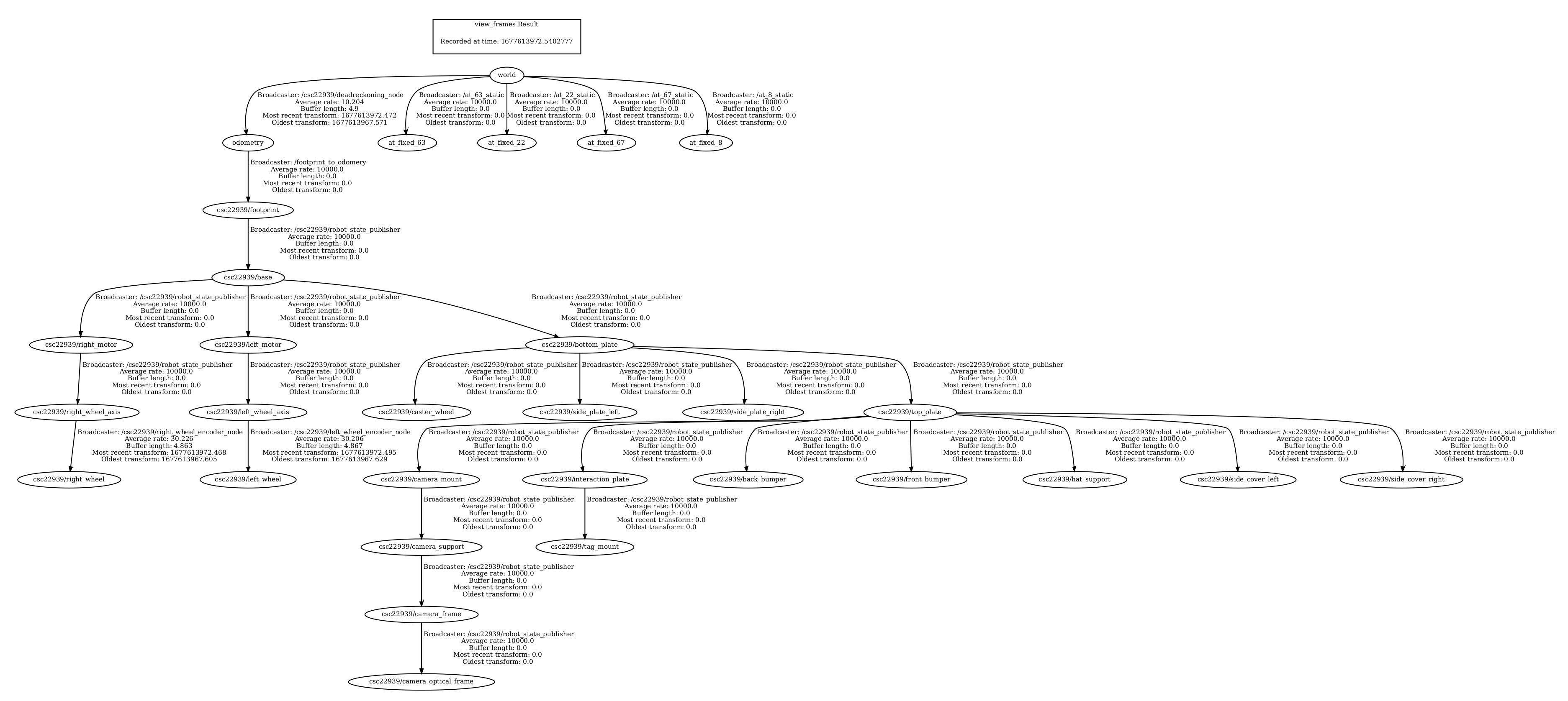 Figure 5: The full transform graph, with both graphs connected by a transfrom from the odometry frame to the footprint frame. The root frame is now
 world. Each arrow denotes a transform between one frame and another.
Two important points I should mention:
- A node cannot have two parents in a transform graph. The reason for this is that all nodes in a graph are connected, so we can generate any transform from one frame to another through a sequence of individual transforms. If we allowed a node to have two parents, we would have to make sure the transforms were consistent. For example, if frame
Ahas parents frameBandCand frameChas parentB, then we would have to make sure the transform fromAtoBwas the exact same as the transform fromAtoCtoB. Furthermore, this would be redundant. Why haveBbe a parent ofAif we can just get the transform fromAtoBviaC? Having multiple parents for a node then just introduces redundancy and complicates the whole system. - Each graph can only have one root frame. If we allowed more than one root frame, then all frames would necessarily have multiple (super-)parent nodes, one for each root frame. This would introduce similar problems as described in (1). Note that although each graph can only have one root frame, we can have multiple, unconnected graphs in our world, and each of these graphs will have its own root frame.
Visualizing Apriltag Detections in RViz
We want to visualize our apriltag detections in RViz in the Duckiebot’s camera frame. This will show the Duckiebot’s estimated location of the apriltag in the real world. Luckily, the code we got from dt-core already does this, so we don’t have to worry about coding in this part. Instead, you can just build and run the project, and then start RViz. You can add an image visualization to see the apriltag detections (the topic you’ll need to read is ROBOT_NAME/apriltag_detector_node/detections/image). Add a robot model visualization and a TF visualization as well.
Below, I’ve included two videos of RViz, where I am broadcasting the apriltag detection images. I also have robot model and TF visualizations. In the videos, I manually drive the Duckiebot around Duckietown to look at the apriltags. When the Duckiebot sees an apriltag, it estimates the location of the apriltag in the real world based on its odometry and broadcasts the estimated location of the apriltag frame as tag/XX, where XX is the apriltag ID.
The static landmark frames for each apriltag indicate where the apriltags are in real life and are called at_fixed_XX, where XX is the apriltag ID. Notice how when the Duckiebot sees an apriltag, it broadcasts the estimated location of that apriltag frame in the camera coordinate system. The estimated location of the apriltag frame is called tag/XX.
From the videos, you should notice one thing. The estimated location of the apriltag frames is quite different from their true position in the real world. There are a few reasons for this:
- We estimate the location of the apriltag frames in the camera frame. The camera frame itself is based on the robot’s odometry, and since our odometry is inaccurate, this means that the estimated location of the apriltag frame is also inaccurate. In effect, the Duckiebot simply looks through its camera and estimates the translation and rotation of the apriltag from its camera. It then estimates the location of the apriltag frame based on its own estimate of its location and rotation (its odometry).
- The Duckiebot is estimating the location and rotation of an object (apriltag) in 3D space (the real world) based solely on its projection onto the camera’s 2D image plane. This is difficult, and although we may be able to get a good idea of the approximate location of the apriltag in the real world, we cannot get its exact physical location because we lose valuable information needed for this prediction when the object in 3D space is projected onto the 2D image plane.
Localizing using Apriltags
Now that we can detect apriltags and estimate their location in the real world, let’s use the apriltags to localize! This involves three steps:
- Get the transformation from the estimated location of the apriltag frame to the wheelbase.
- Apply this transformation to the known (ground truth) location of the apriltag in the real world.
- Teleport the Duckiebot to the position and rotation calculated in (2).
I’ve implemented all of this localizing using apriltags in the AprilPostPros class in the packages/apriltags/src/apriltag_postprocessing_node.py file. All of the code blocks in this section refer to this class.
Preliminaries
First, we’ll need to add a tf.TransformBroadcaster, a tf2_ros.Buffer, a tf2_ros.TransformListener, a subscriber to /tf_static, and a publisher to ROBOT_NAME/deadreckoning_node/update_odom to the AprilPostPros constructor:
1
2
3
4
5
6
7
8
9
10
11
12
13
14
15
16
def __init__(self):
    # ...
    self._tf_bcaster = tf.TransformBroadcaster()
    self.tf_buffer = tf2_ros.Buffer()
    self.tf_listener = tf2_ros.TransformListener(self.tf_buffer)

    self.static_frames = {}
    self.sub_static = rospy.Subscriber(
        "/tf_static", TFMessage, self.static_cb, queue_size=1
    )

    self.update_odom = rospy.Publisher(
        "deadreckoning_node/update_odom", Pose, queue_size=1,
    )

    # ...
The tf.TranformBroadcaster will allow us to broadcast the final Duckiebot location, based on localization using apriltags later. The tf2_ros.Buffer and tf2_ros.TransformListener will allow us to lookup the transforms we need in order to localize with apriltags. The subscriber to /tf_static will allow us to read the static, known (ground-truth) locations of the apriltag frames in real life. The publisher to ROBOT_NAME/deadreckoning_node/update_odom will allow us to teleport the robot to the pose estimated using apriltag localization.
Next, we need to define the callback for the self.sub_static subscriber:
1
2
3
4
5
def static_cb(self, msg):
    for transf in msg.transforms:
        if transf.header.frame_id != "world":
            continue
        self.static_frames[transf.child_frame_id] = transf
This callback will populate the self.static_frames dictionary with all the information about the known apriltags locations in real life. We need this later to localize where our Duckiebot is.
Getting the Transformation from the Estimated Location of the Apriltag Frame to the Wheelbase
The first step in localizing with apriltags is to get the transformation from the estimated location of the apriltag frame to the wheelbase. We already know how to get the estimated location of an apriltag frame (we did this in the previous section); this was done automatically for us by the dt-core implementation. This frame will be named tag/XX, where XX is the apriltag ID. We want to get the transformation from the tag/XX frame to the odometry frame in the world frame coordinates.
Remember the for-else loop in the callback function, which we talked about in the Apriltag Detections section? All of our localization using apriltags code will be placed in this else block. To get the required transformation from estimated location of apriltag frame to the Duckiebot’s wheelbase we just add a few lines to this else block:
1
2
3
4
5
6
7
8
9
10
11
12
13
14
15
16
17
18
19
20
21
22
23
24
25
26
27
28
29
30
31
32
33
34
35
36
37
38
39
40
41
42
43
44
45
46
47
48
49
50
51
52
53
54
55
56
57
58
59
else:
    self._switch_led(id_info)

    # Get the names of each frame we will need later
    tag_id = id_info["tag_id"]
    estimated_tag_frame_id = f"tag/{tag_id}"  # Where duckiebot thinks tag is
    tag_frame_id = f"at_fixed_{tag_id}"       # Ground truth, fixed apriltag location

    # The transformation from ground truth apriltag frame to Duckiebot's
    # updated location, using localization with apriltags
    transformed_frame = "transformed_" + tag_frame_id

    try:
        # We only want to update with an apriltag if we know its static location
        estimate_loc = tag_frame_id in self.static_frames
        if estimate_loc:
            # Get known location of apriltag
            known_loc = self.static_frames[tag_frame_id]
            x = known_loc.transform.translation.x
            y = known_loc.transform.translation.y

            # Get the transform from the robot's estimated location of
            # the apriltag (frame tag/XX) to the robot's odometry frame
            # Use the world coordinate system for these coordinates.
            trans = self.tf_buffer.lookup_transform_full(
                estimated_tag_frame_id,
                rospy.Time(0),
                "odometry",
                rospy.Time(0),
                "world",
            )

            # Broadcast this transform as transformed_at_fixed_XX. This
            # is the transformation from tag/XX -> odometry, and can be applied
            # to the fixed apriltag position (ground truth) to get the current
            # estimate of the robot's position using the apriltag.
            q_rot = [
                trans.transform.rotation.x,
                trans.transform.rotation.y,
                trans.transform.rotation.z,
                trans.transform.rotation.w,
            ]
            t = [
                trans.transform.translation.x,
                trans.transform.translation.y,
                trans.transform.translation.z,
            ]
            self._tf_bcaster.sendTransform(
                t,
                q_rot,
                rospy.Time.now(),
                transformed_frame,
                tag_frame_id,
            )

            # ...

    except (tf2_ros.LookupException, tf2_ros.ConnectivityException, tf2_ros.ExtrapolationException):
        pass
Applying the Transformation to the Known, Ground Truth Apriltag Location
Next, we need to apply the previous transformation to the known, ground truth location of the apriltag. This will give us our Duckiebot’s position using localization with apriltags.
Let’s review what is exactly happening. We have the transformation from the tag/XX frame to odometry frame (call it tag/XX -> odometry). So, we know how to transform from the apriltag’s position to the robot’s position. But remember, the robot’s position and the position of the tag/XX frame are both based on the robot’s odometry which is inaccurate. That is tag/XX will not be at the real location of the apriltag in real life. But, we know that the at_fixed_XX frame will be at the real-life location of the apriltag, so we can apply the transformation from tag/XX -> odometry to the pose of the at_fixed_XX frame to get a better estimate of the robot’s pose than what we have with odometry!
This will also be implemented in the else block above:
1
2
3
4
5
6
7
8
9
10
11
12
13
14
15
16
17
18
19
20
21
22
else:
    # ...

    try:
            # ...

            # Get the transformation from the estimated apriltag
            # position (tag/XX) to the world frame (origin), and apply
            # it at the fixed frame of at_fixed_XX. This is the robot's
            # position, estimated using apriltags.
            at_trans = self.tf_buffer.lookup_transform_full(
                "world",
                rospy.Time(0),
                transformed_frame,
                rospy.Time(0),
                tag_frame_id,
            )

            # ...

    except (tf2_ros.LookupException, tf2_ros.ConnectivityException, tf2_ros.ExtrapolationException):
        pass
Teleport the Duckiebot
The final step in localizing with apriltags is to teleport the Duckiebot to the newly estimated location! Simply add this code to the else block outline above:
1
2
3
4
5
6
7
8
9
10
11
12
13
14
15
16
17
18
19
20
21
22
23
24
25
26
27
28
29
else:
    # ...

    try:
            # ...

            # Pack the previous transform into a pose
            qx = at_trans.transform.rotation.x
            qy = at_trans.transform.rotation.y
            qz = at_trans.transform.rotation.z
            qw = at_trans.transform.rotation.w
            x = at_trans.transform.translation.x
            y = at_trans.transform.translation.y
            z = at_trans.transform.translation.z
            updated_pose_at = Pose()
            updated_pose_at.position.x = x
            updated_pose_at.position.y = y
            updated_pose_at.position.z = z
            updated_pose_at.orientation.x = qx
            updated_pose_at.orientation.y = qy
            updated_pose_at.orientation.z = qz
            updated_pose_at.orientation.w = qw

            # Update the robot's guess of its current position to the
            # estimate using apriltags
            self.update_odom.publish(updated_pose_at)

    except (tf2_ros.LookupException, tf2_ros.ConnectivityException, tf2_ros.ExtrapolationException):
        pass
And that’s it! This codebase should now use odometry to estimate the Duckiebot’s position when an apriltag is not in view, but when an apriltag is in view, the Duckiebot will localize with the apriltag and update its odometry estimate accordingly!
The Final Product
Below I’ve included a video of the final product of our hard work. In this video, I manually drive the Duckiebot in a full circle around Duckietown. When the Duckiebot sees an apriltag, it uses the apriltag to localize. When no apriltag is in sight, the Duckiebot uses odometry to estimate its location.
You can see this in action in the RViz window. As the Duckiebot drives around Duckietown, you can see it using its odometry to figure out where it is (the robot model on the right-hand-side of RViz). Once the Duckiebot sees an apriltag, you can see the robot model on the right-hand-side of RViz jump to its newly estimated location, estimated using localization with the apriltag.
Questions
- Q: Is this a perfect system?
A: This is not a perfect system, we will still have errors in the estimated Duckiebot position, but it will be significantly more accurate than using odometry alone.
- Q: What are the causes for some of the errors?
A: Errors are cause by some of the previously mentioned issues. For example, attempting to predict the real-life 3D location of an apriltag from a 2D projection (and the 3D transformation from apriltag to wheelbase using a 2D projection). Errors are also introduced because our measurements of the ground truth apriltag locations and rotations may not be fully accurate. For example, the $(x, y, z)$ coordinates we set for each apriltag’s known position most definitely have errors, you cannot perfectly measure the apriltag’s position. I’ve also specified certain apriltags to have a 45° yaw angle, but maybe these apriltags actually have a 47° yaw angle or a 45.1° yaw angle, etc. Once again, you cannot perfectly measure the apriltag’s rotation. Furthermore, the camera itself could have issues, maybe the focus wasn’t set properly, and maybe the homography matrix wasn’t constructed accurately.
- Q: What other approaches could you use to improve localization?
- A: We could use other sensors to improve localization. For example, our Duckiebots have a distance sensor. We could use this sensor to more accurately estimate the position of the apriltags and to measure the Duckiebot’s distance from the apriltags. We could also add a camera above Duckietown, looking down at Duckietown, to help with localization as well. We could predict the Duckiebot’s location based on the images from this camera. There are a plethora of ways to improve localization! For example, you could also do the Neanderthal method where every $N$ minutes you stop the Duckiebot, measure its location manually, broadcast this location to the Duckiebot, and then let the Duckiebot continue running its course. This may not be practical, but would still help with localization.
Challenges
When completing this part of the assignment, the big challenge I had was trying to figure out how to use the lookup_transform_full function from tf2_ros. I find documentation for TF2 to be quite bad, so this didn’t help. One of the main things I realized is that in this function, the target_frame parameter is the original frame, and we want to transform to the input_frame using coordinates in the fixed_frame. This is super confusing but was the only way I could get the implementation to work.
The next big challenge I faced was not understanding fully how to get the transformation from the apriltag to the Duckiebot, in order to localize the Duckiebot. At first, I thought I had to get the transformation from the ground truth frame at_fixed_XX to the odometry frame and then apply that transformation to the location of the ground truth frame at_fixed_XX. This doesn’t actually work, because all you’re doing is getting the transformation from the known apriltag location to the odometry frame and then transforming the apriltag location to the location of the odometry frame. This might sound confusing (you might need to read it a few times to see what’s going on), but in effect, this just teleports the Duckiebot to its current location based on its (inaccurate) odometry. It took me a while to figure out that I had to use the transformation from the estimated location of the apriltag frame, tag/XX, to the Duckiebot’s odometry frame, and then apply that transformation to the known location of the ground truth apriltag frame at_fixed_XX.
If you think of the transformation from the tag/XX frame location to the odometry frame location as an operator, $\mathscr{O} = (\text{tag/XX} \to \text{odometry})$, then what we really need to do is update the Duckiebot’s position to $(\text{tag/XX} \to {odometry})(\text{at_fixed_XX}) = \mathscr{O}(\text{at_fixed_XX})$.
References
[2] Classical Robotics Architectures using Duckietown: Unit B-4. Link.
[3] Dynamic Obstacle Avoidance. Link.
[4] Classical Robotics Architectures using Duckietown: Unit B-3. Link.
[5] Coordinate Frames, Transforms, and TF. Link.
[6] Writing a TF2 Broadcaster. Link.
[7] Writing a TF2 Static Broadcaster. Link.